- 41 -
2
2
2
2
2
-5.
Refrigerant piping installation
Flare connection must be applied to the indoor unit and liquid piping of the outdoor
unit, whilst flange connection must be applied to the gas piping of the outdoor unit.
For the branching, brazing connection must be applied.
Warning:
Always use extreme care to prevent the refrigerant gas (R22) from leaking
while using fire or flame. If the refrigerant gas comes in contact with the
flame from any source, such as a gas stove, it breaks down and generates a
poisonous gas which can cause gas poisoning. Never weld in an unventilated
room. Always conduct an inspection for gas leakage after installation of the
refrigerant piping has been completed.
2
2
2
2
2
-5.1. Caution
1
Commercially available piping often contains dust and other materials. Always
blow it clean with a dry inert gas.
2
Use care to prevent dust, water or other contaminants from entering the piping
during installation.
3
Reduce the number of bending portions as much as possible, and make bend-
ing radius as big as possible.
4
Always observe the restrictions on the refrigerant piping (such as rated length,
the difference between high/low pressures, and piping diameter). Failure to do
so can result in equipment failure or a decline in heating/cooling performance.
5
Never use refrigerant to perform an air purge. Always evacuate using a vacuum
pump.
6
Always insulate the piping properly. Insufficient insulation will result in a de-
cline in heating/cooling performance, water drops from condensation and other
such problems.
7
When connecting the refrigerant piping, make sure the ball valve of the out-
door unit is completely closed (the factory setting) and do not operate it until
the refrigerant piping for the outdoor and indoor units has been connected, a
refrigerant leakage test has been performed and the evacuation process has
been completed.
8
Always use a non-oxidizing brazing material for brazing the parts. If a non-
oxidizing brazing material is not used, it could cause clogging or damage to
the compressor unit.
9
Never perform outdoor unit piping connection work when it is raining.
Warning:
When installing and moving the unit, do not charge it with refrigerant other
than the refrigerant specified on the unit.
- Mixing of a different refrigerant, air, etc. may cause the refrigerant cycle to mal-
function and result in severe damage.
2
2
2
2
2
-5.2. Refrigerant piping system
Connection Example
Caution:
•
Total bends are 15 units
.
PEH-7,8,10MYB
PUH-7,8,10MYF
L
=
<
50 m
H
=
<
30 m
A
(mm)
Å
Outdoor unit
ı
Gas pipe size
Ç
Liquid pipe size
PUH-7, 8
ø25.4
ø28.6
ø15.88
PUH-10
ø15.88
B
(mm)
Î
Indoor unit
ı
Gas pipe size
Ç
Liquid pipe size
PEH-7, 8
ø25.4
ø15.88
PEH-10
ø28.6
ø15.88
(1) Single
[Fig.
2
2
2
2
2
-5.2.1]
H
L
2
2
2
2
2
-6.
Additional Refrigerant Charge
2
2
2
2
2
-6.1. Additional refrigerant charge
The mount of refrigerant charged in this unit is a appropriate for 5-meter long
refrigerant pipes.
Refer to the table below and add the corresponding amount of refrigerant if the
pipes are extended.
(The refrigerant is charged in the outdoor unit.)
2
2
2
2
2
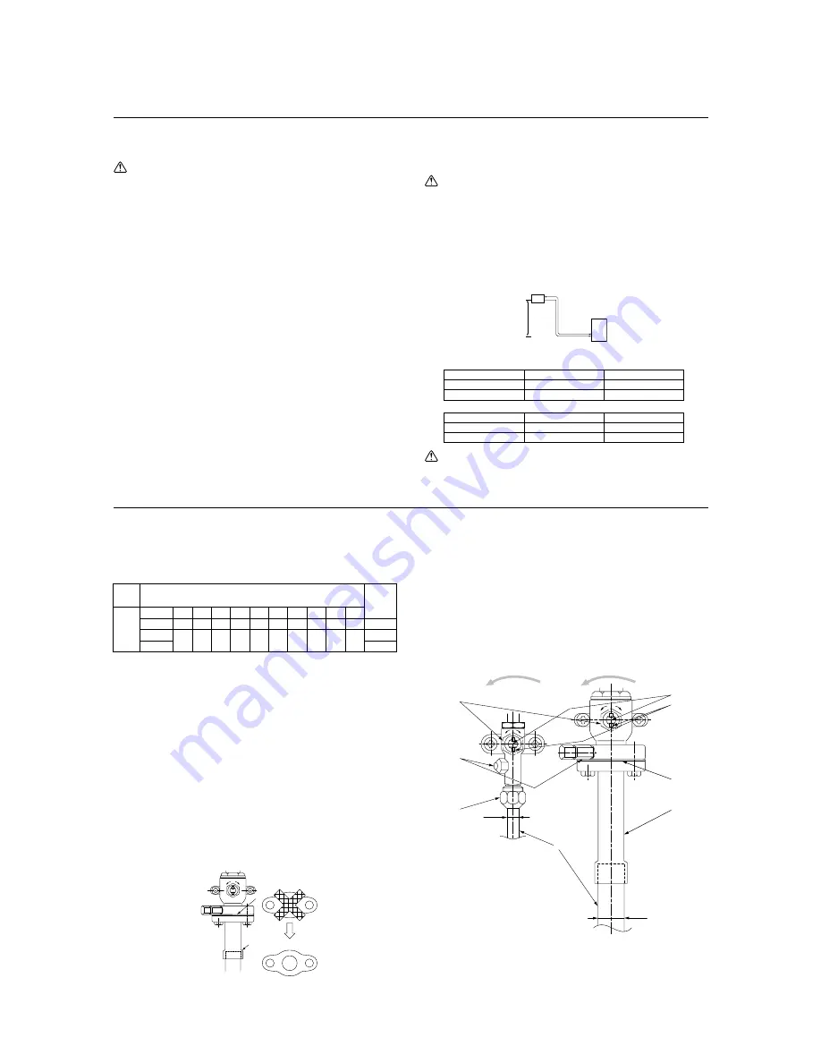
-6.2. Caution for piping connection/valve operation
•
Conduct piping connection and valve operation accurately.
•
The gas side connecting pipe is being assembled for shipment.
1
For brazing to the connecting pipe with flange, remove the connecting pipe
with flange from the ball valve, and braze it at the outside of the unit.
2
During the time when removing the connecting pipe with flange, remove the
seal attached on the back side of this sheet and paste it onto the flange
surface of the ball valve to prevent the entry of dust into the valve.
3
The refrigerant circuit is closed with a round, close-packed packing at the
shipment to prevent gas leak between flanges. As no operation can be
done under this state, be sure replace the packing with the hollow packing
attached at the piping connection.
4
At the mounting of the hollow packing, wipe off dust attached on the flange
sheet surface and the packing. Coat refrigerating machine oil (Ester oil,
ether oil or alkylbenzene [small amount]) onto both surfaces of the pack-
ing.
•
After evacuation and refrigerant charge, ensure that the handle is fully open. If
operating with the valve closed, abnormal pressure will be imparted to the
high- or low-pressure side of the refrigerant circuit, giving damage to the com-
pressor, four-way valve, etc.
•
Determine the amount of additional refrigerant charge by using the formula,
and charge refrigerant additionally through the service port after completing
piping connection work.
•
After completing work, tighten the service port and cap securely not to gener-
ate gas leak.
Refrigerant piping length
Factory
charge
(kg)
5.7
6.6
9.9
charge
mount
R-22
(kg)
unit
PUH-7
PUH-8
PUH-10
5m
0
0
10m
0.8
0.8
15m
1.6
1.7
20m
2.4
2.5
25m
3.2
3.3
30m
4.0
4.2
35m
4.8
5.0
40m
5.6
5.8
45m
6.4
6.7
50m
7.2
7.5
[Fig.
2
2
2
2
2
-6.2.1]
L
M
1
3
E
F
G
H
I
K
J
E
A
B
C
D
O
S
O
S
[Fig.
2
2
2
2
2
-6.2.2]
<A> [Ball valve (gas side)]
(This figure shows the valve in the
fully open state.)
<B> [Ball valve (liquid side)]
A
Valve stem
B
Stopper pin
C
Packing (Accessory)
D
Connecting pipe (Accessory)
E
Open (Operate slowly)
F
Cap, copper packing
G
Service port
H
Flare nut
I
ø15.88
J
ø25.4 PUH- 7, 8
ø28.58 PUH- 10
K
Field piping
L
Close-packed packing
M
Hollow packing
Summary of Contents for PEH series
Page 2: ......


