- 13 -
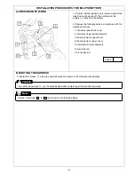
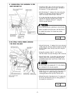
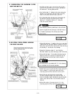
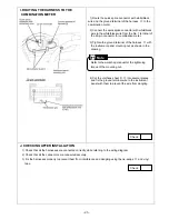
H. ROUTING THE HARNESS TO THE
COMBINATION METER
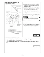
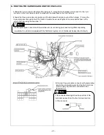
1) Route the quick splice connector with white/black
wire and the ground terminal of the harness
③
to
the combination meter.
2) Connect the quick splice connector with white/black
wire to the black/white wire from the No. 13 terminal
of the 18-pin connector for combination meter.
3) Wrap the connector with the urethane sheet C
④
as shown in the drawing to prevent the connector
from rattling.
4) Tighten the ground terminal of the harness
③
with
the instrument panel mounting nut as shown in the
drawing.
5) Cut the urethane sheet D
④
to an appropriate size
and fix the ground terminal wire to the instrument
panel with it to prevent the wire from dangling.
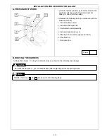
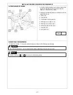
I. CHECKING AFTER INSTALLATION
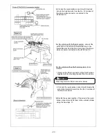
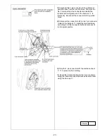
1) Check that all the harnesses are connected correctly while referring to the wiring diagram.
2) Check that all the connectors are connected securely.
3) Fix the harnesses properly to prevent them from interference and dangling using the tie-wraps
⑦
and vinyl
tape.
Check
Check
Refer to the workshop manual for the tightening
torque of the mounting nut.
Note
Summary of Contents for MZ360360EX
Page 6: ... 6 ...
Page 7: ... 7 ...
Page 16: ... 16 ...
Page 17: ... 17 ...
Page 28: ... 28 ...
Page 29: ... 29 ...
Page 42: ... 42 Circuit Diagram ...
Page 43: ... 43 ...
Page 44: ... 44 Troubleshooting P 38 step 2 ...
Page 45: ... 45 P 38 step 2 3 ...
Page 46: ... 46 P 41 step 3 3 ...
Page 47: ... 47 P 51 terminal No 3 P 51 ...
Page 48: ... 48 P 51 P 51 terminal No 13 ...
Page 49: ... 49 P 51 terminal No 24 P 51 terminal No 18 ...
Page 50: ... 50 ...

