

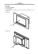
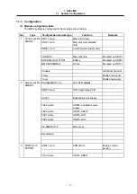


1. OUTLINE
1.1 System Configuration
– 2 –
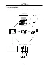
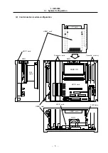
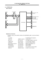
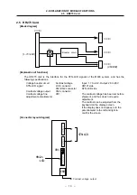
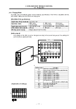
1.1.2 System outline drawing
With the M600 system, connections are made with the drive section through a remote I/O separated
from the control section as shown below.
I/O INTERFACE
HR325/327/335/337
HR371
24VDC
200VAC
LCD
Control section
Display section
Operation section
External power supply PD25
Base I/O unit
Remote I/O unit
Machine electric cabinet
Card-sized I/O
Machine electric cabinet
Servo drive unit/spindle drive unit
Servomotor / spindle motor