
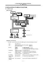
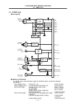


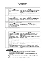


2. EXPLANATION OF MODULE FUNCTIONS
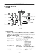
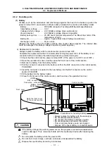
2.7 HR325, 327, 335, 337 Cards
– 16 –
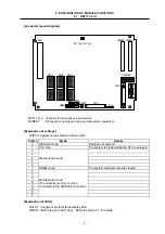
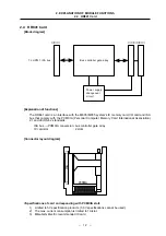
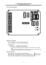
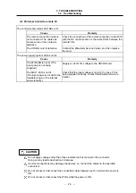
[Connector layout diagram]
CF
32 (Di
2)
CF
31 (Di
1)
CF
33 (Do
1)
CF
34 (Do
2)
CR31
SK
IP
E
NC1
CF1
0
SV
2
SV1
D
CIN
RIO
R
IO1
R
IO2
CS1
CS2
24IN
RAL1
5OUT
RAL2
LED
[Explanation of settings]
CS1: Onboard RIO No. 1 channel No. setting rotary switch
CS2: Onboard RIO No. 2 channel No. setting rotary switch
<Setting method>
0 to 7 : Corresponds to channel Nos. 0 to 7
8 and following : Loop back test mode (for testing)
∗
The CS1 and CS2 settings must always be different for the HR325, 327, 335 and 337
cards.
Always set different channel Nos. for each remote unit and add-on card connected to the
same system. Up to eight channels can be set per system.
[Explanation of LEDs]
24IN (upper side) : LED lit during supply of 24VDC (green)
5OUT (upper side) : LED lit during output of 5VDC circuit power (green)
RAL1 (lower side) : Onboard RIO No. 1 channel communication alarm (red)
RAL2 (lower side) : Onboard RIO No. 2 channel communication alarm (red)
Refer to section
3.1 for details.