

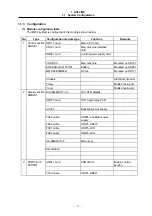


2. EXPLANATION OF MODULE FUNCTIONS
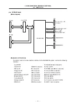
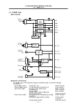
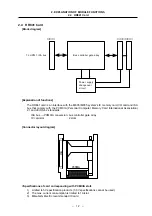
2.1 HR111 Card
– 7 –
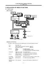
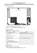
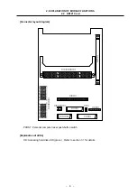
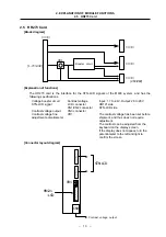
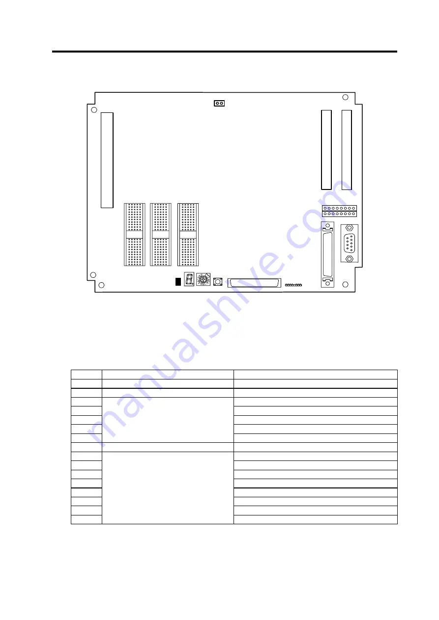
[Connector layout diagram]
NCLD1
0
CF11
RT#0
RT#1
RT#2
AVR
CF10
ENC#2
TEST1&2
CBUS#1 CBUS#2
NCRST
NCSYS
WDER
ISP
DC fan (for 5V)
TEST 1 & 2 : Test pins for maintenance and service
NCREST : NC reset (do not press during normal system operation)
[Explanation of settings]
NCSYS: System mode selection rotary switch
Switch Mode
Details
0
Standard mode
Operation of system 1
1
PLC stop
The system is started while the PLC is stopped.
2
3
4
5
6
Maintenance mode
7
SRAM mode
The system parameter area is cleared.
8
9
A
B
C
D
E
F
Maintenance mode
(The cassette memory must be
connected to the CBUS #2 connector.)
[Explanation of LEDs]
NCLD1 : 7-segment system status display LED
WDER : Watch dog error LED (red) Refer to section 3.1 for details.