


-
-
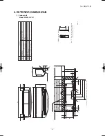
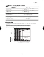
'16 • SRK-T-192
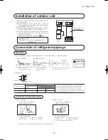
Content
C
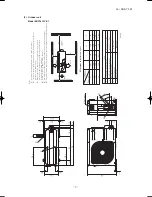
Pipe
/cable draw-out hole
E
Anchor bolt hole
Drain discharge hole
Symbol
B
A
Service valve connectio
n
(
igas side
)
M10
×
4places
φ
20
×
2places
Service valve connectio
n
(
iliquid side
)
D
φ
12.7
(
1
/
2"
)(
Flare
)
φ
6.35
(
1
/
4"
)(
Flare
)
Unit:mm
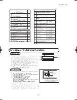
Notes
(1)
It must not be surr
ounded by walls on the four sides.
(2)
The unit must be fixed with anchor bolts. An anchor bolt must not
pr
otrude mor
e than 15mm.
(3)
Wher
e the unit is subject to str
ong winds, lay it in such
a dir
ection that the blower outlet faces perpendicularly
to the dominant wind dir
ection.
(4)
Leave 1m or mor
e space above the unit.
(5)
A wall in fr
ont of the blower outlet must not exceed the units height.
(6)
The model name label is attached on the lower right cor
ner of the fr
ont panel.
40°
40°
138.4
33.5
Ter
minal block
C
B
A
97.7
42.5
15.8
595
63.4
390.6
390.6
69.4
111.6
510
158.4
780
61.9
17.9
14.8
312.5
24.3
351.6
50.6
12
290
E
D
L2
Intake
Outlet
Intake
L3
L1
Minimum installation space
Service space
( )
L4
L2
L3
L4
L1
100
100
250
Open
I
II
Open
250
80
280
III
280
Open
80
75
Examples of
Dimensions
installation
IV
180
Open
80
Open
(2) Outdoor unit
Model SRC18YLV-S1
Summary of Contents for SRK18YLV-S1
Page 2: ......
Page 3: ...TECHNICAL MANUAL ...
Page 9: ... 16 SRK T 192 3 Wireless remote control Unit mm 60 17 3 150 ...
Page 53: ... 50 16 SRK T 192 ...
Page 54: ... 51 16 SRK T 192 PARTS LIST INDOOR UNIT SRK18YLV S1 OUTDOOR UNIT SRC18YLV S1 ...
Page 59: ... 56 16 SRK T 192 CRBE0294 6 13 11 18 12 15 16 3 17 14 2 4 9 8 7 5 1 8 8 10 PANEL FAN ASSY ...