Mitsubishi Heavy Industries SRK18YLV-S1 Technical Manual Download Page 22

-


-

'16 • SRK-T-192

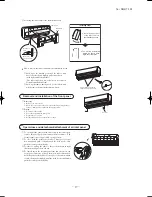
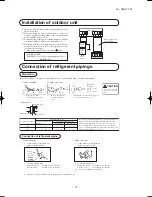
Insulation of connecting portion

  Cover  the  connection  portion  of  the  refrigerant  piping  with  the 

pipe cover and seal them.


If neglecting to do so, moisture occurs on the piping and water 
will drip out.

  Finishing and fixing

  Tie up the piping with wrapping tape, and shape it so that it conforms 

to which the pipe is attached.

  Fix them with clamps as right figure.

Vinyl tape

To  cover  the  connecting  portion  with  insula-
tion materials, cut upper portion and then seal 
it with insulation materials.

Cover the exterior portion with cov-
ering tape and shape the piping so it 
will match the contours of the route 
that  the  piping  to  take. Also  fix  the 
wiring  and  pipings  to  the  wall  with 
clamps.

Insulation

Refrigerant piping
Electrical wiring
Covering tape
Drain hose

Tapping screw

 Additional refrigerant charge
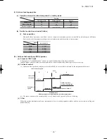
Air purge

  Tighten all flare nuts in the pipings both 

indoor  and  outside  so  as  not  to  cause 
leak.

  Connect  service  valve,  charge  hose, 

manifold  valve  and  vacuum  pump  as  is 
illustrated right.

  Open  manifold  valve  handle  Lo  to  its 

full width, and perform vacuum or evac-
uation.


Continue  the  vacuum  or  evacuation 
operation  for  15  minutes  or  more  and 
check  to  see  that  the  vacuum  gauge 
reads – 0.1 MPa (– 76 cmHg).

  After completing vacuum operation, ful-

ly open service valve (Both gas and liq-
uid sides) with hexagon headed wrench.

  Detach the charge hoses.

  Check for possible leakage of gas in the 

connection parts of both indoor and out-
door.

(three-way valve)

Charge hose (Designed specifically for R410A)

Compound pressure gauge

Pressure gauge

Gauge manifold

(Designed specifically for R410A)

Handle Hi

Vacuum pump

Vacuum pump adapter

(Anti-reverse flow type)

(Designed specifically for R410A)

Charge hose

(Designed specifically for R410A)

Check joint 

-0.1MPa

(-76cmHg)

 Handle Lo

Service valve

Service valve

(two-way valve)

Service valve

cap

Service valve

cap

Service valve cap
tightening torque (N•m)

Check joint blind nut
tightening torque (N•m)

ø6.35  (1/4")

10~12

ø12.7  (1/2")

25~35

20~30

Service valve size

(mm)

Securely tighten the 

service valve cap and the check joint blind nut after adjustment.

  Since the system uses check joints differing in diameter from those found on the conventional models, a charge hose (for R22) presently in use is not 

applicable.

  Please use one designed specifically for R410A.

  Please use an anti-reverse flow type vacuum pump adapter so as to prevent vacuum pump oil from running back into the system.

  Oil running back into an air-conditioning system may cause the refrigerant cycle to break down.
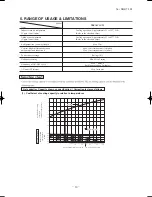
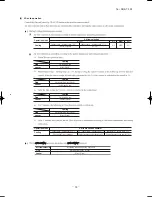
Model

SRK/C18YLV-S1

Additional refrigerant

Less than 15m : Not required

more than 15m : 20g/m

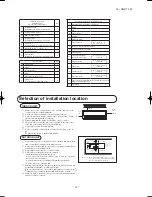
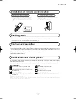
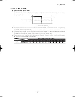
How to relocate or dispose of the unit

  In order to protect the environment, be sure to pump down (recovery of 

refrigerant).

  Pump down is the method of recovering refrigerant from the indoor unit 

to the outdoor unit when the pipes are removed from the unit.

<How to pump down>

  Connect charge hose to check joint.

  Liquid side : Close the liquid valve with hexagon wrench key.


Gas side : Fully open the gas valve.


Carry  out  cooling  operation.  (If  indoor  temperature  is  low,  operate 
forced cooling operation.)

  After low pressure gauge become 0.01MPa, stop cooling operation and 

close the gas valve.
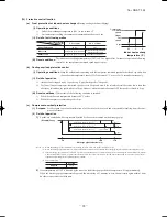
  Forced cooling operation

  Turn on a power source again after a while after turn 

off  a  power  source. Then  press  continually  the  ON/
OFF button 5 seconds or more.

Unit ON/OFF button

Summary of Contents for SRK18YLV-S1

Page 1: ...RESIDENTIAL AIR CONDITIONING TECHNICAL MANUAL PARTS LIST INVERTER WALL MOUNTED TYPE RESIDENTIAL AIR CONDITIONER Split system air cooled cooling only type SRK18YLV S1 Manual No 16 SRK T 192 ...

Page 2: ......

Page 3: ...TECHNICAL MANUAL ...

Page 4: ...louver control 23 4 Custom cord switching procedure 22 3 Auto restart function 2 Unit ON OFF button 22 21 8 Installation location setting 25 11 Outline of automatic operation 27 0VUMJOF PG EFIVNJEJGZJOH 3 PQFSBUJPO 26 0VUMJOF PG DPPMJOH PQFSBUJPO 26 12 Protective control function 28 31 30 5SPVCMFTIPPUJOH QSPDFEVSF G UIF BJS DPOEJUJPOFS SVOT 5SPVCMFTIPPUJOH QSPDFEVSF G UIF BJS DPOEJUJPOFS EPFT OPU ...

Page 5: ...utdoor unit inspection points Phenomenon observed after shortcircuit wire breakage on sensor 9 Checking the indoor electrical equipment How to read the model name Example SRK 18 Y Series code Inverter type Product capacity Model name SRK Wall mounted type SRC Outdoor unit LV S1 ...

Page 6: ...mote control Room temperature control Microcomputer thermostat Operation Display RUN Green TIMER Yellow HI POWER Green 3D AUTO Green Safety devices Compressor overheat protection Overcurrent protection Frost protection Serial signal error protection Fan motor error protection Cooling overload protection Lock rotor protection Installation data Refrigerant piping size O D mm Liquid line φ6 35 1 4 Ga...

Page 7: ...rain hose Liquid piping F E C D B Symbol A 㸦ȭ65㸧 VP16 ȭ6 35 㸦1㸭4 㸧 㸦Flare㸧 Content 㸦ȭ65㸧 Outlet for piping 㸦on both side㸧 G ȭ12 7 㸦1㸭2 㸧 㸦Flare㸧 Note㸦1㸧The model name label is attached ࠉࠉ ࠉon the underside of the panel 60 150 17 3 788 27 60 45 60 45 790 268 17 5 200 39 3 43 2 44 5 102 5 585 102 5 206 5 450 133 5 138 450 202 44 5 7 5 252 2 8 3 㸦Service space㸧 65 㸦Service space㸧 15 50 㸦 Service spac...

Page 8: ...rection that the blower outlet faces perpendicularly to the dominant wind direction 4 Leave 1m or more space above the unit 5 A wall in front of the blower outlet must not exceed the units height 6 The model name label is attached on the lower right corner of the front panel 40 40 138 4 33 5 Terminal block C B A 97 7 42 5 15 8 595 63 4 390 6 390 6 69 4 111 6 510 158 4 780 61 9 17 9 14 8 312 5 24 3...

Page 9: ... 16 SRK T 192 3 Wireless remote control Unit mm 60 17 3 150 ...

Page 10: ... WHITE VARISTOR N TO OUTDOOR UNIT 1 250V 3 15A FUSE L EXCHANGER HEAT WHITE U SENSOR ROOM TEMP R AMP WIRELESS DISPLAY YELLOW WHITE MOTOR FAN 6 SENSOR HEAT EXCH BOARD PRINTED CIRCUIT CNG CNE CNU 1 3 4 5 RED BLACK BLUE BACK UP SW 8 2 2 M 2 SENSOR HUMIDITY CNF BOX CONTROL CNM FLAP MOTOR LOUVER L MOTOR MOTOR LOUVER R 5 5 5 CNX CNY M M M t t ...

Page 11: ...CTIVE FILTER UNIT S R O O S 1 S 2 S R PWB ASSY SUB BK WH WH RD C 2 T1 T2 YE OR PWB ASSY MAIN POWER TRANSISTOR YELLOW GREEN Y G BLACK WHITE RED ORANGE Color OR WH RD BK YELLOW YE BROWN BR DISCHARGE PIPE TEMP SENSOR TH3 COMPRESSOR MOTOR FAN MOTOR ELECTRIC EXPANSION VALVE COIL REACTOR LEGEND R FMo EEV CM OUTDOOR AIR TEMP SENSOR TH2 HEAT EXCHANGER SENSOR TH1 OUTDOOR UNIT TERMINAL BLOCK L N 1 3 2 2 Out...

Page 12: ...nic expansion valve Liquid Capillary tube Outdoor air temperature sensor Muffler Compressor Discharge pipe temperature sensor Cooling cycle Check joint Service valve Heat exchanger sensor Th2 TH3 Room temperature sensor Th1 Gas TH2 Heat exchanger sensor TH1 EEV Capillary tube Heat exchanger Humidity sensor HD 4 PIPING SYSTEM Model SRK18YLV S1 ...

Page 13: ... temperature Upper lower limits Vertical height difference between outdoor unit and indoor unit Refrigerant line one way length Power source voltage Voltage at starting Frequency of ON OFF cycle ON and OFF interval Cooling operation Approximately 21 to 32 D B Refer to the selection chart Cooling operation Approximately 21 to 43 D B Refer to the selection chart Max 15m Outdoor unit is higher Max 15...

Page 14: ...rrection of cooling capacity in relation to one way length of refrigerant piping How to obtain the cooling capacity Piping length m Cooling 7 1 0 10 0 99 15 0 975 20 0 965 25 0 95 30 0 935 SRK18YLV S1 SRK18YLV S1 5000 4875 ...

Page 15: ...n the service valves for liquid line and gas line until completed refrigerant piping work air tightness test and evacuation If the compressor is operated in state of opening service valves before com pleted connection of refrigerant piping work air can be sucked into refrigerant circuit which can cause bust or personal injury due to anomalously high pres sure in the refrigerant Do not put the drai...

Page 16: ...let of outdoor unit It can cause remarkable decrease in performance corrosion and damage of components malfunction and fire Do not install the indoor unit in the locations listed below Be sure to install the indoor unit according to the installation manual for each model because each indoor unit has each limitation Locations with any obstacles which can prevent inlet and outlet air of the unit Loc...

Page 17: ...posed to the direct rays of the sun or the strong rays of the street lighting A place where it can be easily drained A place separated at least 1m away from the television or the ra dio To prevent interfence to images and sounds INDOOR UNIT 10 cm 5 cm 10 cm Left side 60 cm MIN Air intake 10 cm MIN 10 cm MIN Air outlet Air intake No obstacles Service space for electrical parts Right side Standard a...

Page 18: ...ice Space for service 0 Space for service 00 0 0 0 0 0 0 00 Limitations for one way piping length and vertical height difference r h Drilling of holes and fixture sleeve Option parts Inserting sleeve Note 1 Drill a hole with incline of 5 degree from indoor side to outdoor side Indoor side Outdoor side Cut off the sleeve collar in case of drawing piping out to rear Cut off the sleeve collar that ca...

Page 19: ...the connecting wire by wiring clamp ⓔ Attach the lid ⓕ Close the air inlet panel Shaping the pipe Taping of the exterior Hold the bottom of the pipe and change its direction before stretching it and shaping it Tape only the portion that runs through the wall Always tape the crossover wires with the pipe Cautions when piping from the left and the rear center of the unit Top View Remove the screw an...

Page 20: ...achment of air inlet panel Set screws Removing Remove the 2 set screws Move the lower part of the panel forward and push upwards to remove Remove the 3 latches in the upper section Fitting Do remove the air filter Cover the body with the front panel Tighten the 2 set screws Fit the air filter Carry out in the above order To open pull the panel at both ends of lower part and release latches then pu...

Page 21: ...nt B protrusion from the flaring block will vary depending on the type of a flare tool in use If a conventional flare tool is used please use a copper pipe gauge or a similar instrument to check protrusion so that you can keep measurement B to a correct value Copper pipe diameter Clutch type flare tool for R410A Conventional R22 flare tool Clutch type Wing nut type Measurement B mm ø6 35 ø12 7 0 0...

Page 22: ...fically for R410A Handle Hi Vacuum pump Vacuum pump adapter Anti reverse flow type Designed specifically for R410A Charge hose Designed specifically for R410A Check joint 0 1MPa 76cmHg Handle Lo Service valve Service valve two way valve Service valve cap Service valve cap Service valve cap tightening torque N m Check joint blind nut tightening torque N m ø6 35 1 4 10 12 ø12 7 1 2 25 35 20 30 Servi...

Page 23: ...erly Battery Cover Fixing to pillar or wall Conventionally operate the wireless remote control by holding in your hand Avoid installing it on a clay wall etc Screws CAUTION Do not use new and old batteries together Installations test check points Check the following points again after completion of the installation and before turning on the power Conduct a test run again and ensure that the unit o...

Page 24: ...flow rate with lamp CLEAN indicator Indicates during CLEAN operation ON OFF TIMER indicator Indicates during ON OFF TIMER operation AIR FLOW indicator Shows selected flap and louver mode 3D AUTO indicator Indicates during 3D AUTO operation HI POWER ECONO MODE indicator Indicates during HIGH POWER ECONOMY mode operation Transmission procedure When each button on the remote control is pressed with t...

Page 25: ...y both boards If only one board is modified receiving and operation cannot be done a Modifying the indoor unit s printed circuit board Take out the printed circuit board from the control box and cut off jumper wire J13 using wire cutters After cutting of the jumper wire take measures to prevent contact with the other the lead wires etc b Modifying the wireless remote control i Remove the battery i...

Page 26: ...prox 45 Approx 60 Angle of Flap from Horizontal Center installation Remote control display Right end installation Left end installation Angle of louver Left Approx 45 Left Approx 45 Left Approx 20 Left Approx 30 Center Left Approx 20 Right Approx 20 Center Right Approx 45 Right Approx 20 Left Approx 20 Center Right Approx 20 Right Approx 30 Right Approx 45 Louver stopped Swing Spot Wide In COOL DR...

Page 27: ...wing Fixed Flap Louver Cooling Up down Swing Center Fixed Wide Fixed Flap Louver Cooling Horizontal blowing Fixed Operation mode Indoor temp Setting temp 2 C Cooling Air flow direction contorol 2 C Indoor temp Setting temp 5 C Indoor temp Setting temp 5 C The control in 4 continues dehumidifying dehumidifying Control returns to the control in 2 Control returns to the control in 1 Wide Fixed Flap A...

Page 28: ...location Take the air conditioning unit s location into account and adjust the left right airflow rang Center Installa 2 Press the AIR AIRFLOW or more The installation l 1 If the air condi button to stop The installation l 4 Press the ON O The air condition Press within 60 s installation locati Air conditioner installation location and airflow r The diagram below indicates the airflow ranges corre...

Page 29: ...fication and not to control the humidity to the target condition Indoor outdoor unit control the operation condition to reduce the humidity and also prevent over cooling i Indoor unit fan speed and compressor are controlled by the area which is selected by the temperature difference Indoor unit fan speed Area D C B A Me speed Indoor unit fan speed Lo speed STOP Limited Lower than normal cooling op...

Page 30: ...tomatic operation or when the automatic operation is selected during cooling or dehumidifying operation the unit is operated in the previous operation mode d Setting temperature can be adjusted within the following range There is the relationship as shown below between the signals of the wireless remote control and the setting temperature Signals of wireless remote control Display 6 5 4 3 2 1 0 1 ...

Page 31: ... Reset conditions When either of the following condition is satisfied 1 When the outdoor air temperature becomes 40ºC or less 2 When the compressor command speed is 0rps c Compressor overheat protection i Purpose It is designed to prevent deterioration of oil burnout of motor coil and other trouble resulting from the com pressor overheat ii Detail of operation 1 Speeds are controlled with temperat...

Page 32: ... under for more than 30 seconds the unit enters first in the stop mode and then stops the entire system i Serial signal transmission error protection i Purpose Prevents malfunction resulting from error on the indoor outdoor signals ii Detail of operation 1 When the outdoor unit control cannot receive signals from the indoor unit If the compressor is operating and a serial signal cannot be received...

Page 33: ...OTING PROCEDURES FOR ELECTRICAL EQUIPMENT 1 Cautions 2 Items to check before troubleshooting 3 Troubleshooting procedure If the air conditioner does not run at all Important YES YES YES NO NO NO NO YES Reference Reference AC proced wireless source source satisfied ...

Page 34: ... 31 16 SRK T 192 09 SRK DB 087D 4 Troubleshooting procedure If the air conditioner runs NO NO NO NO YES YES YES YES 32 33 36 33 36 ...

Page 35: ...sor wire poor connector connection Outdoor PCB is faulty 4 time flash Keeps flashing The inverter output current compressor motor current exceeds the set value during compressor start The air conditioner stops Compressor locking open phase on compressor output shortcircuit on power transistor closed service valve 1 time flash ON When there is an emergency stop caused by trouble in the outdoor unit...

Page 36: ...or unit Data are recorded for up to 5 previous occurrences Data which are older than the 5th previous occurrence are erased In addition data on the temperature of each sensor room temperature indoor heat exchanger outdoor heat exchanger outdoor air temperature discharge pipe remote control information operation switching fan speed switching are recorded when trouble occurs so more detailed informa...

Page 37: ...revious 3 times previous 4 times previous 5 times previous i wireless mode mode wireless Wireless remote control setting wireless 43 safe 3 43 43 safe 09 SRK DB 087D Wireless remote control setting Fan speed mode Operation mode mode mode Displayed data Temperature setting 21ºC 22ºC 23ºC 24ºC 25ºC Displays the reason for the stop error code the previous time an error was displayed Displays the reas...

Page 38: ...e start Compressor lock Compressor wiring short circuit Compressor output is open phase Outdoor PCB is faulty Compressor start fails 42 times in succession and the reason for the final failure is current cut After the compressor starts it stops due to current cut at less than 20 rps When operation is stopped by current cut at 20 rps or higher When the DC voltage exceeds 390V When it is judged that...

Page 39: ...e recovered Rotor lock Rotor lock Protective control operation Indoor unit fan motor is abnormal Discharge pipe sensor is abnormal anomalous stop Indoor heat exchanger sensor is abnormal anomalous stop Outdoor heat exchanger sensor is abnormal anomalous stop Anti condensation control Anti frost control Compressor overheating protection control Refrigeration cycle system protective control Connecti...

Page 40: ...ight 1 s digit Display pattern when in service mode Fan speed mode when there is an abnormal stop 2 time flash 3 time flash 4 time flash AUTO HI MED LO 6 time flash 7 time flash operation mode and fan speed mode becomes as follows HI POWER ECONO Mode Operation mode Fan speed mode 0 5 sec 1 5 sec RUN light 10 s digit TIMER light 1 s digit 11 second interval 0 5 sec OFF ON OFF ON mode COOL Fan mode ...

Page 41: ...84 94 55 45 35 25 15 5 5 15 25 35 45 55 65 75 85 95 56 46 36 26 16 6 6 16 26 36 46 56 66 76 86 96 57 47 37 27 17 7 7 17 27 37 47 57 67 77 87 97 58 48 38 28 18 8 8 18 28 38 48 58 68 78 88 98 59 49 39 29 19 9 9 19 29 39 49 59 69 79 89 99 No does not sound Sensor name Room temperature sensor Indoor heat exchanger sensor Outdoor air temperature sensor Outdoor heat exchanger sensor 64ºC 64ºC 64ºC 64ºC ...

Page 42: ... 126 146 48 28 8 8 28 48 68 88 108 128 148 50 30 10 10 30 50 70 90 110 130 150 52 32 12 12 32 52 72 92 112 132 54 34 14 14 34 54 74 94 114 134 56 36 16 16 36 56 76 96 116 136 58 38 18 18 38 58 78 98 118 138 No does not sound Sensor value displayed when the error code is normal 64ºC 0 5 sec 0 1 sec 1 5 sec 11 second interval 0 5 sec OFF ON OFF ON OFF ON temperature information data Buzzer sound If ...

Page 43: ... 40 16 SRK T 192 09 SRK DB 087D Service data record form Operation mode Fan speed mode Wireless r Wireless r Wireless r Wireless r Wireless r Wireless r ...

Page 44: ...70 0 10 Discharge pipe sensor temperature characteristics Indoor fan motor error Broken sensor wire connector poor connection 0 0 20 40 60 80 100 120 135 20 40 60 80 100 120 140 160 180 Temperature C Resistance k Defective fan motor connector poor connection defective indoor PCB 46 for the fan motor and indoor PCB check pro Power source reset Is it normalized Malfunction by temporary noise Replace...

Page 45: ... short circuit Compressor output is open phase Outdoor PCB is faulty Service valve is closed EEV is faulty Compressor faulty Current safe stop Overload operation compressor lock overcharge 49 1 417Ω U V 1 392Ω V W 1 435Ω W U or more at 20ºC Inspect outdoor air temperature sensor ...

Page 46: ...43 16 SRK T 192 09 SRK DB 087D Over heat of compressor Gas shortage defective discharge pipe sensor Error of signal transmission Wiring error including power cable defective indoor outdoor PCB 41 source ...

Page 47: ...fective fan motor connector poor connection defective outdoor PCB See pages 49 for the fan motor and outdoor PCB check pro After making sure the fan motor and outdoor PCB are nor Power source reset Is it normalized Malfunction by temporary noise Replace fan motor If the error persists after replacing the fan motor replace the outdoor PCB the fan motor and outdoor ourdoor PCB outdoor Replace outdoo...

Page 48: ...cks and oscillating between DC 0 and 20V Inspect power source for outdoor unit Replace fuse Replace indoor PCB Is the fuse burnt out 3 15 A YES YES YES NO NO NO b Indoor unit fan motor check procedure 1 Indoor PCB output check Sensor Phenomenon Short circuit Disconnected wire Heat exchanger sensor Ourdoor air temperature sensor Discharge pipe sensor Compressor stop The compressor cannot pick up it...

Page 49: ...d 20V Replace indoor PCB YES b Indoor unit fan motor check procedure 1 Indoor PCB output check 2 Fan motor resistance check FMI DC15V Indoor PCB DC 308 336V DC several V 4 6 V CNU GND Blue Yellow White Black Red Measuring point Resistance when normal Measuring point Voltage range when normal k M ...

Page 50: ...eration Faulty part other than fan motor YES Fan motor is faulty YES YES YES NO NO NO Replace the faulty part and the fuse Test run then the unit for checking Is there any damage on the internal circuit of fan motor Check the resistance value to judge See pages 46 to 49 Is the fuse blown on the indoor and outdoor PCB Is there any faulty part fan motor etc See pages 45 to 49 Replace the fuse on the...

Page 51: ...outdoor unit CAUTION HIGH VOLTAGE High voltage is produced in the control box Don t touch electrical parts in the control box for 5 minutes after the unit is stopped Color symbol Power source and serial signal inspection 1 to 2 AC 220V 2 to 3 Normal if the voltage oscillates between DC 0 and approx 20V Power source 1 Phase 220V 50Hz S R BK WH G1 YG IN IN 250V 20A FUSE YG BK TB R CNTH 2 TH1 TH2 TH3...

Page 52: ...valve as a separate unit Measuring point Resistance when normal b Outdoor unit fan motor check procedure Measuring point Voltage range when normal DC15V DC several 4 7V Outdoor PCB GND DC280 373V CNFAN Red Blue Brown Orange White FM0 1 2 3 i ii iii DC iv i Fan motor resistance check Measuring point Resistance when normal Blue Blue k ii source 280 373V ...

Page 53: ... 50 16 SRK T 192 ...

Page 54: ... 51 16 SRK T 192 PARTS LIST INDOOR UNIT SRK18YLV S1 OUTDOOR UNIT SRC18YLV S1 ...

Page 55: ... 52 16 SRK T 192 CRAE0229 2 14 9 8 14 14 10 10 12 12 24 11 21 17 22 13 4 5 1 31 28 30 35 35 6 3 3 4 16 22 25 21 7 27 26 32 34 33 29 18 20 15 22 19 23 PANEL FAN ASSY ...

Page 56: ...1 14 RKW935C200 COLLAR 6 15 RKX129A010 BRACKET MOTOR A 1 1 1 1 2 16 RKX129A011 BRACKET MOTOR B 1 1 1 1 2 17 RKX129A012 BRACKET MOTOR C 1 1 1 1 2 18 RKX144A001 LINK 1 1 1 1 2 19 RKX144A002 CRANK A 1 1 1 1 2 20 RKX144A003 CRANK B 1 1 1 1 2 21 RKW144A204 CRANK C 2 1 1 1 2 22 SSA512T096 MOTOR STEPPING 3 1 1 1 2 23 RKS504A100G HARNESS ASSY 1 1 1 1 2 FOR FLAP MOTOR 24 RKS504A100 HARNESS ASSY 1 1 1 1 2 F...

Page 57: ... 54 16 SRK T 192 CRAE0254 21 17 23 24 22 18 1 8 5 7 6 3 2 4 15 9 11 12 16 19 13 14 20 25 10 HEAT EXCH CONTROL ...

Page 58: ...SA564A132 FUSE CURRENT 1 1 1 2 4 F 3A 13 SSA551A163L SENSOR ASSY 1 1 1 2 4 INCL SENSOR ROOM TEMP HEAT EXCH 14 SSA561B702B BLOCK TERMINAL 1 1 1 2 2 T 15 RKX011G603A LABEL WIRING 1 16 SSA551B017 SENSOR HUMIDITY 1 1 1 2 4 17 RKX503A301 DISPLAY ASSY 1 1 1 2 3 18 RKX505A007 PWB ASSY DISPLAY 1 2 2 4 8 19 RKJ941F001A SPRING LEAF 1 20 RKX502A001 CONTROL ASSY REMOTE 1 2 3 5 10 21 RMA008A011D PARTS STANDARD...

Page 59: ... 56 16 SRK T 192 CRBE0294 6 13 11 18 12 15 16 3 17 14 2 4 9 8 7 5 1 8 8 10 PANEL FAN ASSY ...

Page 60: ...3 6 SSA944B036B HANDLE 1 7 RCV142A001 COVER TB 1 8 SSA913A034F SCREW TAP 26 4 8 9 SSA913A034G SCREW TAP 1 4 12 10 SSA913A008F SCREW TAP 1 4 10 11 RCV116A006 BRACKET ASSY 1 12 SSA512T094 MOTOR DC 1 2 2 4 8 13 RCV116A003 BRACKET MOTOR U 1 14 RCV141A002D PLATE BAFFLE 1 15 SSA431B253 PROPELLER 1 1 1 2 4 16 SSA914B007AC NUT TH 1 17 RCV111A001 BASE ASSY 1 1 1 1 2 18 W011D04X008 TAP SCREW CRS TRS2 6 FOR ...

Page 61: ... 58 16 SRK T 192 CRBE0342 7 24 23 26 23 27 CONTROL ASSY 16 15 14 25 11 12 1 13 28 23 9 10 19 18 22 20 21 17 2 5 6 4 8 3 GAS LIQ HEAT EXCH CONTROL ...

Page 62: ... 1 1 2 3 8 12 SSA914C013A NUT FLANGE 2 13 SSA941C346A CUSHION RUBBER 3 14 RSA932C004 GASKET COVER 1 15 RSA947K005 COVER TERMINAL 1 1 1 2 4 16 SSA914C016 NUT FLANGE 1 17 RCT505A005RA PWB ASSY MAIN 1 2 2 4 8 18 RCT505A004C PWB ASSY SUB 1 2 2 4 8 19 RMC011G008A LABEL WIRING 1 20 SSA561B723 BLOCK TERMINAL 1 1 1 2 2 21 SSA564A136A FUSE CURRENT 1 1 1 2 4 F 20A 22 SSA564B088 HOLDER FUSE 1 23 SSA551A216L ...

Page 63: ...L AIR CONDITIONING TECHNICAL MANUAL PARTS LIST Copyright MITSUBISHI HEAVY INDUSTRIES LTD Because of our policy of continuous improvement we reserve the right to make changes in all specifications without notice C ...

Reviews: