


-
45
-
'16 • SRK-T-192
'09•SRK-DB-087D
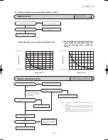
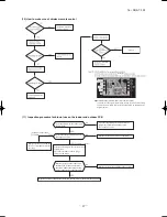
Outdoor fan motor error
Rotor lock
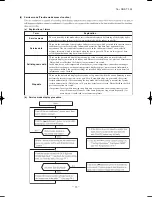
(8) Phenomenon observed after shortcircuit, wire breakage on sensor
(a) Indoor unit
Defective fan motor, connector poor
connection, defective outdoor PCB
Defective compressor, defective
outdoor PCB
Sensor
Operation
mode
Phenomenon
Shortcircuit
Disconnected wire
Room temperature
sensor
Cooling
Heating
Heat exchanger
sensor
Cooling
Heating
Humidity sensor
(1)
Cooling
Heating
■
Humidity sensor operation
Failure mode
Control input circuit resding
Air conditioning system operation
①
②
①②
①
②
See page 42.
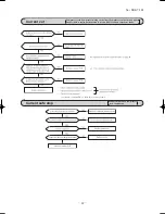
(8) Phenomenon observed after shortcircuit, wire breakage on sensor
(a) Indoor unit
Sensor
Phenomenon
Shortcircuit
Disconnected wire
Room temperature
sensor
Heat exchanger
sensor
Humidity sensor
■
Humidity sensor operation
Failure mode
Control input circuit reading
Air-conditioning system operation
①
②
①②
①
②
Freezing cycle system protection trips and stops the compressor.
circuit
'09•SRK-DB-087D
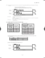
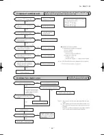
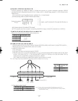
(9) Checking the indoor electrical equipment
(a) Indoor PCB check procedure
(b) Outdoor unit
Is there voltage between terminal
blocks
①
and
②
? (AC220/230/240
V)
Indoor electrical components
are normal.
Is the voltage between terminal
blocks
②
and
③
oscillating between
DC 0 and 20V?
Inspect power source
for outdoor unit.
Replace fuse.
Replace indoor PCB.
Is the fuse burnt out? (3.15 A)
YES
YES
YES
NO
NO
NO
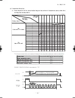
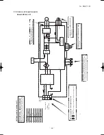
(b) Indoor unit fan motor check procedure
1) Indoor PCB output check
① ④
⑤
2) Fan motor resistance check
⑥
⑤
④
③
②
①
⑥
⑤
④
③
②
①
FM
I
DC15V
Indoor PCB
DC 308~336V
DC several V
(4~6 V)
CNU
(–)
GND
Blue
Yello
w
White
Black
Red
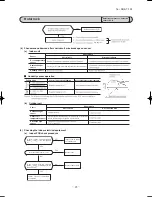
Sensor
Phenomenon
Short circuit
Disconnected wire
Heat exchanger
sensor
Ourdoor air
temperature sensor
Discharge pipe
sensor
Measuring point
Resistance when normal
① − ③
−
④ − ③
−
Measuring
point
Resistance when
normal
① − ③
④ − ③
⑤ − ③
⑥ − ③
k
M
Compressor stop.
The compressor cannot pick up its speed owing to the current
safe so that the designed capacity is not achieved.
'09•SRK-DB-087D
(9) Checking the indoor electrical equipment
(a) Indoor PCB check procedure
(b) Outdoor unit
Is there voltage between terminal
blocks
①
and
②
? (AC 220/230/240
V)
Indoor electrical components
are normal.
Is the voltage between terminal
blocks
②
and
③
oscillating between
DC 0 and 20V?
Inspect power source
for outdoor unit.
Replace fuse.
Replace indoor PCB.
Is the fuse burnt out? (3.15 A)
NO
YES
YES
NO
YES
NO
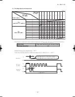
(b) Indoor unit fan motor check procedure
1) Indoor PCB output check
① ④
⑤
2) Fan motor resistance check
⑥
⑤
④
③
②
①
⑥
⑤
④
③
②
①
FM
I
DC15V
Indoor PCB
DC 308-336V
DC several V
(4-6 V)
CNU
(–)
GND
Blue
Yello
w
White
Black
Red
Sensor
Operation
mode
Phenomenon
Shortcircuit
Disconnected wire
Heat exchanger
sensor
Cooling
Heating
Ourdoor air
temperature sensor
Cooling
Heating
Discharge pipe
sensor
All modes
Measuring point
Resistance when normal
① − ③
−
④ − ③
−
Measuring
point
Voltage range when
normal
① − ③
④ − ③
⑤ − ③
Defrosting is performed for 10 minutes at approx. 35 minutes.
Defrosting is performed for 10 minutes at approx. 35 minutes.
k
M
−
−
Summary of Contents for SRK18YLV-S1
Page 2: ......
Page 3: ...TECHNICAL MANUAL ...
Page 9: ... 16 SRK T 192 3 Wireless remote control Unit mm 60 17 3 150 ...
Page 53: ... 50 16 SRK T 192 ...
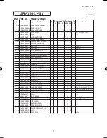
Page 54: ... 51 16 SRK T 192 PARTS LIST INDOOR UNIT SRK18YLV S1 OUTDOOR UNIT SRC18YLV S1 ...
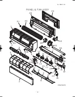
Page 59: ... 56 16 SRK T 192 CRBE0294 6 13 11 18 12 15 16 3 17 14 2 4 9 8 7 5 1 8 8 10 PANEL FAN ASSY ...