


34
2. Installation and Wiring
2.5 Main circuit terminals
2.5
Main circuit terminals
2.5.1
Details on the main circuit terminals
2.5.2
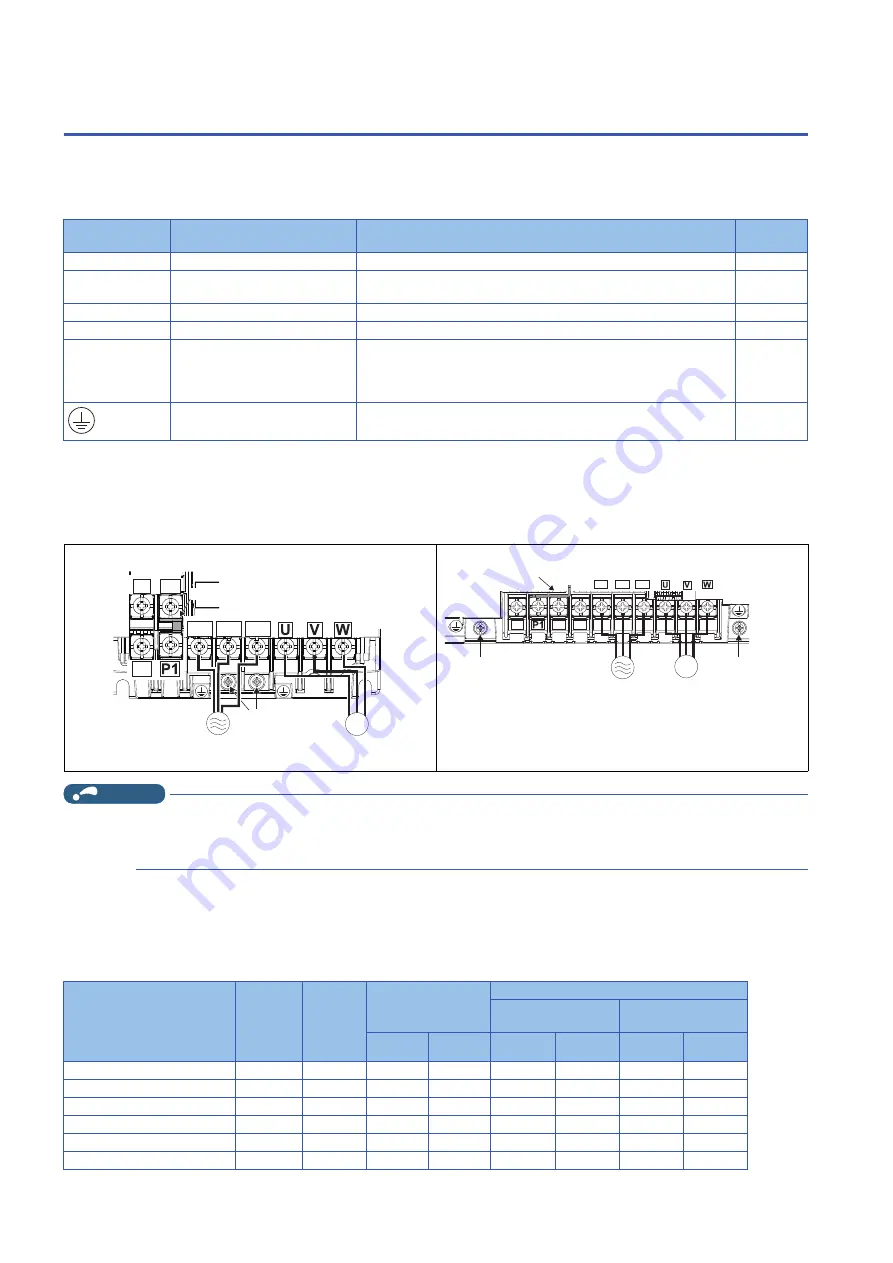
Main circuit terminal layout and wiring to power
supply and motor
NOTE
• Make sure the power cables are connected to the R/L1, S/L2, and T/L3. (Phase need not be matched.) Never connect the
power cable to the U, V, and W of the inverter. Doing so will damage the inverter.
• Connect the motor to U, V, and W. (The phases must be matched.)
2.5.3
Applicable cables and wiring length
For the ND rating
• 575 V class (575 V input power supply, without a power factor improving AC or DC reactor)
Terminal symbol
Terminal name
Terminal function description
Refer to
page
R/L1, S/L2, T/L3
AC power input
Connect these terminals to the commercial power supply.
—
U, V, W
Inverter output
Connect these terminals to a three-phase squirrel cage motor or a PM
motor.
—
P/+, PR
Brake resistor connection for
Connect a brake resistor across terminals P/+ and PR.
P/+, N/-
Brake unit connection
Connect the brake unit.
—
P/+, P1
DC reactor connection for
Remove the jumper across terminals P/+ and P1, and connect a DC
reactor.
When a DC reactor is not connected, the jumper across terminals P/+
and P1 should not be removed.
Earth (ground)
For earthing (grounding) the inverter chassis. Be sure to earth (ground)
the inverter.
FR-E860-0017(0.75K) to 0040(2.2K)
FR-E860-0061(3.7K) to 0120(7.5K)
N/- P/+
PR
R/L1 S/L2 T/L3
M
Motor
Power supply
Jumper
Earthing (grounding)
terminal
R/L1
S/L2
T/L3
N/-
P/+
PR
M
Power supply
Motor
Jumper
Earthing (grounding)
terminal
Earthing (grounding)
terminal
Applicable inverter model
FR-E860-[]
Terminal
screw
size
Tightening
torque
(N·m)
Crimp terminal
Cable gauge
HIV cables, etc.
(mm
2
)
AWG/MCM
R/L1, S/L2,
T/L3
U, V, W
R/L1, S/L2,
T/L3
U, V, W
R/L1, S/L2,
T/L3
U, V, W
0017(0.75K)
M4
1
2-4
2-4
2
2
14
14
0027(1.5K)
M4
1
2-4
2-4
2
2
14
14
0040(2.2K)
M4
1
2-4
2-4
2
2
14
14
0061(3.7K)
M4
1
2-4
2-4
2
2
14
14
0090(5.5K)
M4
1
2-4
2-4
2
2
14
14
0120(7.5K)
M4
1
5.5-4
2-4
3.5
2
12
14


