Page 28
Purpose:
Measuring
Instrument
Test Point
Measuring
Range
Input Signal
Ext. Trigger
Input Terminal
Symptom:
Purpose
Measuring
Instrument
Test Point
Measuring
Range
Input Signal
Ext. Trigger
Input Terminal
Symptom:
MODEL: WT-42313 / WT-42413
-----
-----
------
------
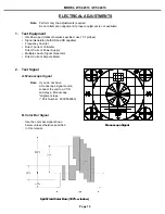
Monoscope
Video Input
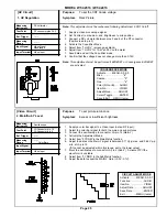
[Video Circuit]
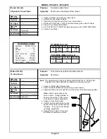
7. Black Level
To set the black level of the picture.
Excess or insufficient brightness.
1. Supply a Monoscope signal to a Video Input.
2. Activate the Adjust Mode, Video Chroma Function.
3. Adjust Item “2 SBRT” so the 0% and 10% black levels on the gradation scale
are the same. (SBRT data should fall between 19 and 25.)
4. Press ENTER to save data.
7. Exit the Service Mode.
40% 30% 20% 10%
50% 0%
0%
0%
60% 70% 80% 90%
GRADATION SCALE
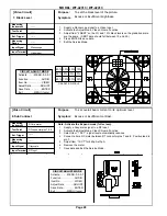
DC ma meter
DT connector pins 7 & 8
------
-----
Grayscale
RF Input
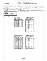
To set overall beam current to its’ optimum level.
Excess or insufficient contrast.
Note: Activate the Expand mode (full screen).
1. Supply a Grayscale signal to a RF Input.
2. Activate the Adjust Mode, Video Chroma Function.
3. Select Item “1 SCT”, signal level automatically reduces.
4. Connect a 3ma DC meter between DT connector pins 7 and 8. Positive lead to
pin 7.
5. Adjust Item “1 SCT” for 440µA ±10µA
.
6. Remove the meter.
7. Save data and Exit the Service Mode.
[Video Circuit]
8. Sub Contrast
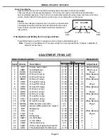
CIRCUIT ADJUST MODE
Activate …….. MENU-0-3-5-7
Function …...………..AUDIO
Item No. ……….…….VIDEO
Adjust Data ….…….ADJUST
Save Data …. ………ENTER
Exit …………..MENU (twice)
CIRCUIT ADJUST MODE
Activate …….. MENU-0-3-5-7
Function …...………..AUDIO
Item No. ……….…….VIDEO
Adjust Data ….…….ADJUST
Save Data …. ………ENTER
Exit …………..MENU (twice)
Summary of Contents for WT-42313
Page 2: ......
Page 11: ...MODEL WT 42313 WT 42413 Page 11 PCB Locations Major Parts Locations ...
Page 53: ...MODEL WT 42313 WT 42413 Page 53 POWER SUPPLY ...
Page 54: ...MODEL WT 42313 WT 42413 Page 54 VIDEO COLOR ...
Page 55: ...MODEL WT 42313 WT 42413 Page 55 SYNC SIGNAL PATH ...
Page 56: ...MODEL WT 42313 WT 42413 Page 56 DEFLECTION HV ...
Page 57: ...MODEL WT 42313 WT 42413 Page 57 HV REGULATION ...
Page 58: ...MODEL WT 42313 WT 42413 Page 58 X RAY PROTECT ...
Page 59: ...MODEL WT 42313 WT 42413 Page 59 SOUND SIGNAL PATH ...
Page 60: ...MODEL WT 42313 WT 42413 Page 60 CONVERGENCE ...
Page 61: ...MODEL WT 42313 WT 42413 Page 61 CONTROL CIRCUITRY ...

