MODEL: WT-42313 / WT-42413
Page 34
Purpose:
Measuring
Instrument
Test Point
Measuring
Range
Input Signal
Ext. Trigger
Input Terminal
Symptom:
-----
-----
------
-----
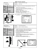
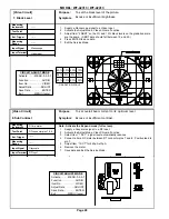
To converge red, green and blue at the center of the screen
Color edging over the entire picture.
Preliminary
Degauss the shield cover and bracket unit of the CRT assembly and chassis.
DO NOT
degauss the CPM Assemblies.
HD mode
1. Supply an HD Monoscope signal to the DTV Inputs.
2. Select the DTV Inputs as the signal source (Input button).
3. Enter the Convergence Coarse mode.
4. Set the data for the “HSTA” and “VSTA” items to:
GREEN
RED
BLUE
HSTA = 0
HSTA = 50
HSTA = -50
VSTA = 0
VSTA = 0
VSTA = 0
5. In the Coarse Green mode:
• Center the Green Raster using the Green Centering Magnet.
• Rotate the Green Deflection Yoke to correct any tilt.
6. In the Coarse Red mode, use the Red Centering Magnet to converge
red on the green at the center of screen. Correct any red tilt with the Red
Deflection Yoke.
7. In the Coarse Blue mode, repeat Step 6 using the Blue Centering magnet and
the Blue Deflection Yoke.
8. Exit the Convergence mode.
SD mode
1. Supply an NTSC Monoscope signal to a Video Input.
2. Select the Monoscope as the signal source (Input button).
3. Enter the Convergence Coarse Green mode.
4. If needed, center the green raster using “1 HSTA” and “2 VSTA” adjustments.
5. In the Coarse Red mode, use “1 HSTA” and “2 VSTA” adjustments to converge
the red on the green at the center of the screen.
6. In the Coarse Blue mode, repeat step 5 to converge the blue of the green.
7. Exit the Convergence Mode
[Convergence Circuit]
16. Centering and Static
Convergence
NTSC -- Monoscope
HD -- Monoscope
Video & DTV Inputs
CONVERGENCE MODE
Activate ……..MENU-0-3-5-9
Misc. ……………….……"6"
Coarse………………..…."5"
Fine ……………………..."4"
Color (R,G or B)……AUDIO
Item No………….…..VIDEO
Adjust/Move……….ADJUST
Cursor Toggle….…..ENTER
Save & Exit…..MENU (twice)
Summary of Contents for WT-42313
Page 2: ......
Page 11: ...MODEL WT 42313 WT 42413 Page 11 PCB Locations Major Parts Locations ...
Page 53: ...MODEL WT 42313 WT 42413 Page 53 POWER SUPPLY ...
Page 54: ...MODEL WT 42313 WT 42413 Page 54 VIDEO COLOR ...
Page 55: ...MODEL WT 42313 WT 42413 Page 55 SYNC SIGNAL PATH ...
Page 56: ...MODEL WT 42313 WT 42413 Page 56 DEFLECTION HV ...
Page 57: ...MODEL WT 42313 WT 42413 Page 57 HV REGULATION ...
Page 58: ...MODEL WT 42313 WT 42413 Page 58 X RAY PROTECT ...
Page 59: ...MODEL WT 42313 WT 42413 Page 59 SOUND SIGNAL PATH ...
Page 60: ...MODEL WT 42313 WT 42413 Page 60 CONVERGENCE ...
Page 61: ...MODEL WT 42313 WT 42413 Page 61 CONTROL CIRCUITRY ...


