


─ 91 ─
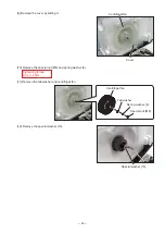
Orifice
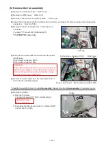
(6) Remove the fan assembly
[1] Remove the heat exchanger. ... Refer to (2).
[2] Remove the PCB cover. ... Refer to (3).
[3] Remove the thermistor and element guide. ... Refer to (4).
[4] Lower the circuit board (control circuit board) to provide a work space for disconnecting and connecting the
connectors. ... Refer to (5) [3].
[8] Remove the orifice.
a. Remove the screw.
(1 screw: Spl screw PTT 4X14, indicated by )
Tightening torque
: 1.1 ± 0.2 N.m
b. Disengage the tabs (three locations, indicated by )
and remove the orifice.
* Steps
[8]
through
[13]
refers to the
EA fan assembly
.
Disassemble the
SA fan assembly
in the similar manner.
Lead clip
[5] Remove the lead clip fixing screw to disconnect the
connector.
(1 screw: PTT screw 4x12, indicated by )
* VL-500CZPVU-L type only
SA fan motor connector: CN10
Motor lead
EA fan motor connector: CN9
Power circuit board
[6] Disconnect the motor lead connectors from the power
circuit board.
SA fan motor connector: CN10
EA fan motor connector: CN9
Precaution
When disconnecting the motor connectors, make sure
that the power supply is turned off. Even when the fan
motor is stopped, disconnecting the live-line connec-
tors will cause a motor malfunction.
[7] Remove the motor leads from the metal plate hook of
the control box (indicated by ).


