


6
GB
D
F
SW
I
NL
E
P
30
46
30
30
120
83.5
C
A
B
D
(1)
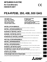
[Fig.11.1.1]
(2)
(3)
A
Remote controller pro-
file
B
Required clearances
surrounding the re-
mote controller
C
Temperature sensor
D
Installation pitch
C
Wall
D
Conduit
E
Lock nut
F
Bushing
G
Switch box
H
Remote controller cord
I
Seal with putty
F
H
C
D
E
G
I
I
B-1.
B-2.
I
<A> For installation in the switch box:
<B> For direct installation on the wall
select one of the following:
<A>
For installation in the switch box
<B> For direct installation on the wall
C
Switch box for two pieces
D
Remote controller cord
E
Cross-recessed, pan-head screw
G
Seal the remote controller cord service entrance with putty
H
Wood screw
11
11.1
11.2
11.3
[Fig.11.2.1]
[Fig.11.3.1]
[Fig.11.3.2]
AB
TB6
A
B
A
To TB5 on the indoor unit
B
Terminal block TB6 in remote controller
No polarity
10.1
10
[Fig.10.1.1]
A
Outdoor unit
B
Indoor unit
C
Main remote controller
D
Subordinate remote controller
E
Standard (Refrigerant address = 00)
F
Refrigerant address = 01
G
Refrigerant address = 02
H
Refrigerant address = 03
I
Refrigerant address = 14
J
Refrigerant address = 15
1
1
2
2
2
A
A
B
A
B
B
B
F
G
J
E
C
A
D
* In case of PEA-200, 250
* In case of PEA-400, 500
1
1
2
2
B
B
B
C
D
A
No.1
A
No.2
A
No.1
A
No.2
A
No.1
A
E
F
G
H
I
J
No.2
H
D
E
D
C
G
KB79U753H01-illust
10.9.27, 17:50
6