


M series
C-578
MULTI SYSTEM Inverter Heat Pump
MUL
TI
SYSTEMS
INST
ALLA
TION
PROCEDURE
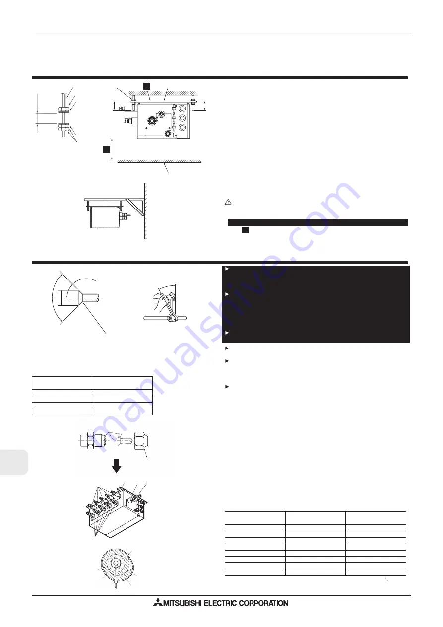
6. Mounting the Branch Box
(mm)
(1) Install the suspension bolts (procure locally) at the specified pitch (Fig. 4-2, 4-3).
(2) Fit the washers and nuts (
,
, procure locally) to the suspension bolts.
(Fig. 6-1)
(3) Hang the unit on the suspension bolts.
(4) Fully tighten the nuts (check ceiling height).
(5) Use a level to adjust the branch box to the horizontal.
When unit is hung and nuts tightened.
Suspension bolt
Nuts
Washer (with cushion)
Ensure that cushion faces downwards
Washer (without cushion)
Nut (procure locally)
Suspension bolt
Ensure that this face is always installed upwards.
Ceiling board
Note:
* Refer to “4-1”.
Caution:
• Always install the unit horizontally.
• This unit may be installed suspended from the ceiling.
•
This unit may only be installed vertically, as shown in the left diagram.
(Side
is facing up.)
• Incorrect installation may result in the drain overflowing.
Fig. 6-1
(
)
A
K
K
*
03
.ni
M
05
.ni
M
* Purchase an appropriate
bracket locally if the unit
is to be mounted on a
wall.
lla
W
Wall mount
Fig. 6-2
7. Installing refrigerant piping
Connect the liquid and gas pipes of each indoor unit to the same end con-
nection numbers as indicated on the indoor unit flare connection section of
each Branch Box. If connected to wrong end connection numbers, it doesn’t
work normally. (Fig. 7-1)
When connecting indoor units, make sure to connect refrigerant pipes and
connection wires to the appropriate connection ports marked with match-
ing alphabets. (Ex. A, B, C, D, E)
Note:
Be sure to mark all the local refrigerant piping (liquid pipes, gas pipes, etc.) for
each indoor unit designating clearly which room it belongs in. (Ex. A, B, C, D, E)
List indoor unit model names in the name plate on the control box of Branch
Box (for identification purposes).
To prevent water dripping from the refrigerant piping, install sufficient ther-
mal insulation.
When using commercially available refrigerant piping, ensure that both liq-
uid and gas piping are wrapped with commercially available thermal insula-
tion materials (insulation materials at least 12 mm thick and able to with-
stand temperatures in excess of 100 °C).
Refer to the installation manual of the outdoor unit when creating a vacuum
and opening or closing valves.
(1) Remove the flared nuts and caps from the branch box.
(2) Flare the ends of the liquid and gas piping, and apply refrigeration oil (procure
locally) to the flared seat.
(3) Connect the refrigerant piping immediately. Always tighten the flared nuts to the
torque specified in the table below using a torque wrench and double spanner.
(4) Press the pipe covers
and
on the liquid piping against the unit and wrap to
hold in place.
(5) Press the pipe covers
and
on the gas piping against the unit and wrap to
hold in place.
(6) Apply the supplied bands
at a position 10 - 20 mm from each end of the pipe
covers (
).
(7) If the indoor unit is not connected, fit the supplied pipe covers (with caps,
and
) to the branch box refrigerant piping connections to prevent condensation drip-
ping from the pipes.
(8) Clamp the pipe covers (
) in place with the supplied bands
.
Flare nut tightening torque
Table 2
Copper pipe O.D.
Flare nut O.D.
Tightening torque
(mm)
(mm)
(N·m)*
ø
8
1
-
4
1
7
1
5
3
.
6
ø
2
4
-
4
3
2
2
5
3
.
6
ø
2
4
-
4
3
2
2
2
5
.
9
ø
1
6
-
9
4
6
2
2
5
.
9
ø
1
6
-
9
4
6
2
7
.
2
1
ø
2
8
-
8
6
9
2
7
.
2
1
ø
2
8
-
8
6
9
2
8
8
.
5
1
ø
0
2
1
-
0
0
1
6
3
8
8
.
5
1
Fig. 7-1
Flare cutting dimensions
Table 1
Copper pipe O.D.
Flare dimensions
(mm)
øA dimensions (mm)
ø6.35
8.7 - 9.1
ø9.52
12.8 - 13.2
ø12.7
16.2 - 16.6
ø15.88
19.3 - 19.7
Flare cutting dimensions
Flare nut tightening torque
90
°±0.5°
øA
R0.4~R0.8
45°±2°
Fig. 7-2
Fig. 7-3
05
.ni
M
* 1N·m
10 kgf·cm
K
Summary of Contents for M-SERIES
Page 6: ...M series C WALL MOUNTED ...
Page 38: ...WALL MOUNTED Outdoor Unit M series WIRING DIAGRAM WALL MOUNTED C 36 MUH GD80VB OUTDOOR UNIT ...
Page 40: ...WALL MOUNTED Outdoor Unit M series WIRING DIAGRAM WALL MOUNTED C 38 OUTDOOR UNIT MUZ FD50VA ...
Page 42: ...WALL MOUNTED Outdoor Unit M series WIRING DIAGRAM WALL MOUNTED C 40 OUTDOOR UNIT MUZ FD50VABH ...
Page 45: ...WALL MOUNTED Outdoot Unit M series WIRING DIAGRAM WALL MOUNTED C 43 MUZ GE42VA OUTDOOR UNIT ...
Page 46: ...WALL MOUNTED Outdoor Unit M series WIRING DIAGRAM WALL MOUNTED C 44 MUZ GE42VAH OUTDOOR UNIT ...
Page 47: ...WALL MOUNTED Outdoot Unit M series WIRING DIAGRAM WALL MOUNTED C 45 MUZ GE50VA OUTDOOR UNIT ...
Page 48: ...WALL MOUNTED Outdoor Unit M series WIRING DIAGRAM WALL MOUNTED C 46 MUZ GE50VAH OUTDOOR UNIT ...
Page 50: ...WALL MOUNTED Outdoor Unit M series WIRING DIAGRAM WALL MOUNTED C 48 MUZ HC25VA OUTDOOR UNIT ...
Page 192: ...WALL MOUNTED Inverter Heat Pump M series INSTALLATION PROCEDURE WALL MOUNTED C 190 ...
Page 271: ...FLOOR STANDING MFZ KA VA Series M series OPERATION FLOOR STANDING C 269 ...
Page 272: ...FLOOR STANDING MFZ KA VA Series M series OPERATION FLOOR STANDING C 270 f i save OPERATION ...
Page 289: ...CEILING CASSETTE Inverter Heat Pump M series INSTALLATION PROCEDURE CEILING CASSETTE C 287 ...
Page 290: ...CEILING CASSETTE Inverter Heat Pump M series INSTALLATION PROCEDURE CEILING CASSETTE C 288 ...
Page 292: ...CEILING CASSETTE Inverter Heat Pump M series INSTALLATION PROCEDURE CEILING CASSETTE C 290 ...
Page 293: ...CEILING CASSETTE Inverter Heat Pump M series INSTALLATION PROCEDURE CEILING CASSETTE C 291 ...
Page 294: ...CEILING CASSETTE Inverter Heat Pump M series INSTALLATION PROCEDURE CEILING CASSETTE C 292 ...
Page 300: ...CEILING CASSETTE M series CEILING CASSETTE C 298 ...


