
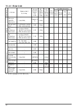


159
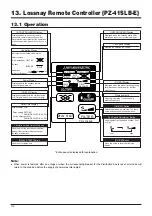
12. Installation method
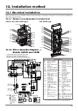
12.1 Electrical installation
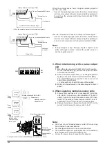
With this product, the wiring installation method will vary according to the design of the system. Perform electrical installation for
each of the required sections.
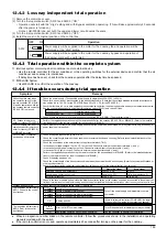
12.1.1 Names of components in control box
LGH-50 and LGH-100RX types
LGH-200RX type
SW5
TM1
LED4
LED1
LED2
LED6
TB5
SA2
SA1
Bush
Bush
SW4
SW3
SW1
TM3
TM2
SW2
Earth pole
PE
L
N
DC 24V 2A DC 5V 100mA
AC240V 2A AC220V 100mA
MAX
MIN
Operation monitor output
DC 24V 1A DC 5V 100mA
AC240V 1A AC220V 100mA
MAX
MIN
Malfunction monitor output
M
2
M
1
7
8
9
3
1
S
B
A
6
5
4
1
3
2
cable
TH2 (RA)
(Invalid in EU)
220V - 60HZ
220-240V - 50HZ
POWER SUPPLY
CN5
LS
M-NET-transmissiion cable
a-contact
TR
C
C
ZNR101
250V6.3A
FUSE
C101
DSA1
ZNR102
BROWN
CN8-2
RED
CN8-1
5
1
5
1
SW4
HIGH
EXTRA
×
3
×
4
×
1
FAN MOTOR
SUPPLY
HIGH
CN9
CN10
FAN MOTOR
EXHAUST
BLACK
GREY
YELLOW
ORANGE
WHITE
BLUE
HIGH
EXTRA
HIGH
×
5
×
2
SW3
×
8
×
7
TM3
10
External control input
3
Shield wire
a-contact
TM2
(non-polar)
Mr. Slim
24V DC
12V or
Uncharged
41SLB-E
52SF-E
Transmissiion
Lossnay unit
Max 15 units
TB5
CN32
GREEN/YELLOW
TM1
S2
S1
1
1
6
CN1
CN6
CN2
CN7
High/Low select connector
Unchaged
Low
High
CN16
GM
CN16
PZ-
PZ-
TH1 (OA)
BREKER
BLUE
BROWN
YELLOW
RED
BROWN
BROWN
ORANGE
ORANGE
GREY
GREY
BLUE
BLUE
WHITE
WHITE
SW1
SW2
SW5
SA2
SA1
N
L
SW1
SW4
SW3
SW4
SW3
TM1
Cord Clip
LED6
SA1
SA2
SA2
SA1
LED2
TM3
TM3
LED1
TB5
TM2
Bush
SW5
SW2
SW1
SW5
SW2
LED4
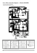
12.1.2 Wire connection diagram -----
Models LGH-50 and 100RX
* Connect the wires shown as dotted lines.
* Be sure to connect the grounding wire.
* Breaker should be provided by the customer.
Symbol explanation
• PZ-41SLB-E and PZ-52SF-E cannot be used simultaneously.
M1:
Motor for exhaust fan
M2:
Motor for supply fan
C:
Capacitor
GM:
Motor for Bypass move-
ment
LS:
Microswitch
TH1:
Thermistor for outside air
TH2:
Thermistor for return air
SW1:
Switch (Main/Sub change)
SW2,5: Switch (Function selec-
tion)
SW3:
High/E.High select switch
(Exhaust fan)
SW4:
High/E.High select switch
(Supply fan)
TM1:
Terminal block
(Power supply)
TM2:
Terminal block
(Transmission cable and
external control input)
TM3:
Terminal block (Monitor
output)
TB5:
Terminal block
(M-NET Transmission
cable)
S1,S2: Connector (Power sup-
ply)
TR:
Control circuit trans-
former
X7:
Relay contact (For opera-
tion monitor output)
X8:
Relay contact (For mal-
function monitor output)
CN1:
Connector
(Transformer primary)
CN2:
Connector
(Transformer secondary)
CN5:
Connector
(Thermistor)
CN6:
Connector
(Microswitch)
CN7:
Connector (Motor for
bypass operation)
CN8-1: Tab connector
(Fan motor)
CN8-2: Tab connector
(Fan motor)
CN9:
Connector (Fan motor)
CN10: Connector (Fan motor)
CN16: Connector (High/Low
switch)
CN32: Connector (Remote
control selection)
SA1:
Address setting rotary
switch
(10 digit)
SA2:
Address setting rotary
switch
(1 digit)
LED1: Inspection indicator lamp
LED2: Inspection indicator lamp
LED4: Power supply indicator
lamp
LED6: M-NET indicator lamp
MARK
: Indicates ter-
minal block
: Connector
: Board inser-
tion connector or
fastening connec-
tor of control
board
Summary of Contents for Lossnay PZ-41SLB-E
Page 4: ...CHAPTER 1 Ventilation for Healthy Living Lossnay Unit ...
Page 17: ......
Page 18: ...CHAPTER 2 Lossnay Construction and Principle ...
Page 24: ...CHAPTER 3 General Technical Considerations ...
Page 41: ......
Page 42: ...CHAPTER 4 Characteristics ...
Page 56: ...53 CHAPTER 4 Characteristics ...
Page 57: ...54 CHAPTER 4 Characteristics ...
Page 59: ......
Page 60: ...CHAPTER 5 System Design Recommendations ...
Page 68: ...CHAPTER 6 Examples of Lossnay Applications ...
Page 83: ......
Page 84: ...CHAPTER 7 Installation Considerations ...
Page 88: ...CHAPTER 8 Filtering for Freshness ...
Page 96: ...CHAPTER 9 Service Life and Maintenance ...
Page 98: ...CHAPTER 10 Ventilation Standards in Each Country ...
Page 101: ......
Page 102: ...CHAPTER 11 Lossnay Q and A ...
Page 108: ...Lossnay Remote Controller ...
Page 109: ......
Page 197: ...MEMO ...
Page 198: ...Y04 002 Jul 2004 MEE ...