


147
Do the capacity of the main power supply on/off unit and wiring span meet specification?
Checkpoint
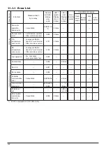
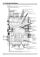
11.2 Items to Check
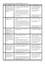
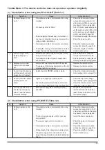
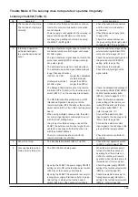
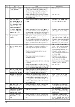
Trouble Mode 1: The system will not start properly.
Initialization checklist from installation to operation (Table 1-1)
After checking the system, check the points below up to operation.
1
No.
2
Is the specified power supplied to the Lossnay power terminal (TM1)? (refer to page 161)
3
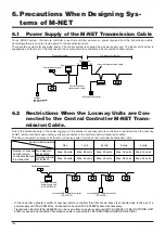
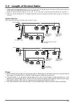
Is the wiring length of the transmission cable within specifications?
When using PZ-41SLB-E:
Overall extension within 500 m
When using M-NET:
Maximum power supply length within 200 m, maximum distance between ends
within 500 m (refer to page 139)
4
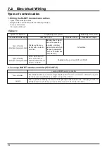
Does the transmission cable meet regulations? (Type, diameter) (refer to page 163)
5
Is the transmission cable wired at least 5 cm away from the power supply cable?
6
Are multiple transmission or signal cables wired to the same power cable duct?
7
Are multiple transmission cables wired with multi core cables?
8
Is the transmission cable connected to the terminal unit?
(PZ-41SLB-E to TM2
5
,
6
; M-NET to TB5
A
,
B
)
9
Is the transmission cable securely connected to the Lossnay terminal unit? (refer to page 163, 165)
10
When not using M-NET
If using 1 Lossnay unit, is the Main/Sub change switch (SW1) on the Lossnay circuit board set to “Main”?
If using 2 or more Lossnay units, is the Main/Sub switch set to “Main” on only one unit, and the other units are set
to “Sub”? (refer to page 164)
11
When using M-NET
Is the address switch on the Lossnay circuit board (SA1, SA2) set to the correct number? (refer to page 166)
12
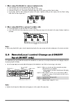
When using external control input
Do the specifications of the external signal match specifications of signals that can be input to the Lossnay? (refer to page 163)
13
When the external input signal is a pulse signal
Is the pulse input switch (SW2-2) on the Lossnay circuit board set to ON? (refer to page 164)
14
When the external signal is 12V DC, 24V DC, or Mr. Slim (A-control) signal
Is it connected to
1
,
2
on the Lossnay external control input terminal unit (TM2)?
15
When the external signal is an uncharged a-contact signal
Is it connected to
1
,
3
on the Lossnay external control input terminal unit (TM2)?
16
When M-NET is not being used
Is the external input signal connected to the Lossnay set to “Main”?
17
Is the signal cable length within wiring specifications?
12V DC, 24V DC signal:
Within limitation of the external device
Uncharged a-contact signal: Within 500 m
Mr. Slim (A-control) signal:
Within 500 m
18
Is the signal cable wired at least 5 cm away from the power supply cable?
19
Is the output capacity of the Lossnay operation monitor/error monitor within specifications?
Operation monitor output: Maximum 240V AC/24V DC 2A, minimum 220V AC/5V DC 100 mA
Error monitor output:
Maximum 240V AC/24V DC 1A, minimum 220V AC/5V DC 100 mA
20
Are the power supply cable, transmission cable, signal cable, etc., securely connected to the proper terminals?
21
Are the settings for the Mai/Sub switch, address switch, and function select switch correct?
Summary of Contents for Lossnay PZ-41SLB-E
Page 4: ...CHAPTER 1 Ventilation for Healthy Living Lossnay Unit ...
Page 17: ......
Page 18: ...CHAPTER 2 Lossnay Construction and Principle ...
Page 24: ...CHAPTER 3 General Technical Considerations ...
Page 41: ......
Page 42: ...CHAPTER 4 Characteristics ...
Page 56: ...53 CHAPTER 4 Characteristics ...
Page 57: ...54 CHAPTER 4 Characteristics ...
Page 59: ......
Page 60: ...CHAPTER 5 System Design Recommendations ...
Page 68: ...CHAPTER 6 Examples of Lossnay Applications ...
Page 83: ......
Page 84: ...CHAPTER 7 Installation Considerations ...
Page 88: ...CHAPTER 8 Filtering for Freshness ...
Page 96: ...CHAPTER 9 Service Life and Maintenance ...
Page 98: ...CHAPTER 10 Ventilation Standards in Each Country ...
Page 101: ......
Page 102: ...CHAPTER 11 Lossnay Q and A ...
Page 108: ...Lossnay Remote Controller ...
Page 109: ......
Page 197: ...MEMO ...
Page 198: ...Y04 002 Jul 2004 MEE ...