background image

7 Communication Using MC Protocol

65

FX

3U

-ENET-ADP User's Manual

1

Introduc

tion

2

Specifi

cation

3

Sy

stem


Configurati

on

4

Ins
tal

lation

5

Wi

rin

g

6

Introduction of 

Functi

on

s

7

C

omm
uni
cation 

U

sing 

M

C

 Protocol

8

The O

perati

on 

of G
X

 W

ork

s2

9

Troubl
es

hooti

ng

A

Li

st of S

peci
al 

Dev
ices

7.5 Device Memory Read/Write

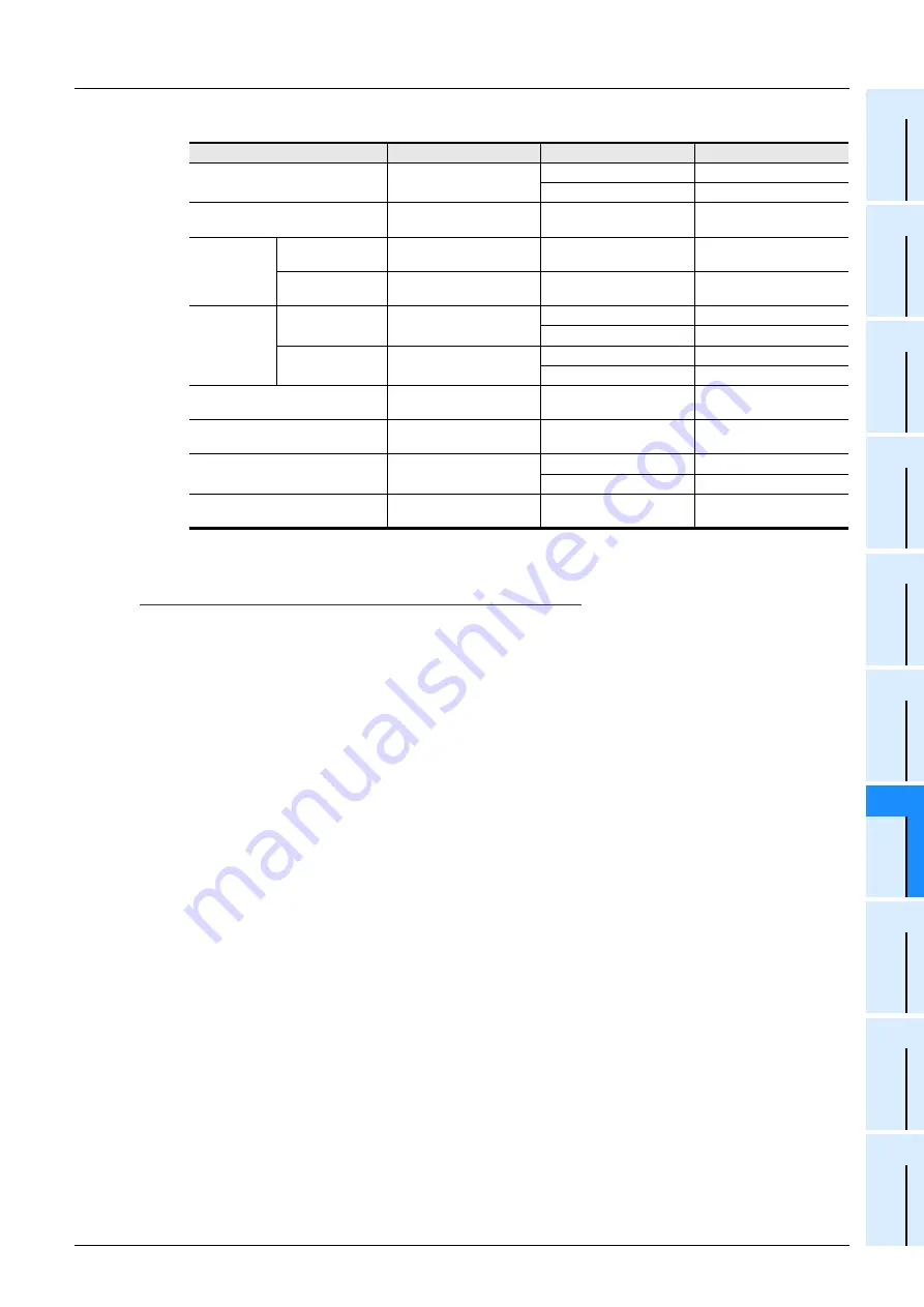
b) The following table outlines the device codes and numbers.

*1. It is not possible to specify D7999 or lower and D8000 or higher at the same time.
*2. It is not possible to specify C199 or lower (16 bits) and C200 or higher (32 bits) at the same time.

Caution

• Bit devices and word devices are classified according to the following.

Bit devices : X, Y, M, S, T (contact), C (contact)
Word devices :T (current value), C (current value), D, R

• When word units are designated, always make the head device number of a bit device a multiple of 16 (0, 

16... in decimal representation).
For X and Y is expressed in octadecimal, the device numbers that can be designated are X00, X20, X40,,, 
or Y00, Y20, Y40,,,.
Also, special auxiliary relays M8000 or later can be specified (8000 + multiples of 16).

• The special auxiliary relays (M8000 to M8511) and special data registers (D8000 to D8511)

are divided into read only, write only and system use registers.
If writing takes place outside the writing enabled range, a PLC error may occur.
For details of special auxiliary relays and special data registers, refer to the Programming Manual and 
Appendix A.

Device

Device code

Device range

Device number

Data register

*1

D

(44H, 20H)

D0 to D7999

0000 to 1F3FH

D8000 to D8511

1F40 to 213FH

Extension register

R

(52H, 20H)

R0 to R32767

0000 to 7FFFH

Timer

Current value

TN

(54H, 4EH)

T0 to T511

0000 to 01FFH

Contact

TS

(54H, 53H)

T0 to T511

0000 to 01FFH

Counter

Current value

*2

CN

(43H, 4EH)

C0 to C199

0000 to 00C7H

C200 to C255

00C8 to 00FFH

Contact

CS

(43H, 53H)

C0 to C199

0000 to 00C7H

C200 to C255

00C8 to 00FFH

Input

X

(58H, 20H)

X0 to X377

0000 to 00FFH

Output

Y

(59H, 20H)

Y0 to Y377

0000 to 00FFH

Auxiliary relay

M

(4DH, 20H)

M0 to M7679

0000 to 1DFFH

M8000 to M8511

1F40 to 213FH

State

S

(53H, 20H)

S0 to S4095

0000 to 0FFFH

Summary of Contents for FX3U-ENET-ADP

Page 1: ...FX3U ENET ADP USER S MANUAL ...

Page 2: ......

Page 3: ... following components should be included an emergency stop circuit a protection circuit an interlock circuit for opposite movements such as normal vs reverse rotation and an interlock circuit to prevent damage to the equipment at the upper and lower positioning limits 2 Note that when the PLC main unit detects an error during self diagnosis such as a watchdog timer error all outputs are turned off...

Page 4: ...re to properly wire to the terminal block European type in accordance with the following precautions Failure to do so may cause electric shock equipment failures a short circuit wire breakage malfunctions or damage to the product The disposal size of the cable end should follow the dimensions described in the manual Tightening torque should follow the specifications in the manual Twist the end of ...

Page 5: ...d When this adapter is installed or removed from the panel make sure to externally cut off all phases of the power supply Failure to do so may cause malfunction or failure of this adapter 18 Reference Please contact a certified electronic waste disposal company for the environmentally safe recycling and disposal of your device 18 Reference The product is a precision instrument During transportatio...

Page 6: ... 4 Safety Precautions Read these precautions before use MEMO ...

Page 7: ... can take it out and read it whenever necessary Always forward it to the end user 2012 MITSUBISHI ELECTRIC CORPORATION Manual number JY997D45801 Manual revision A Date 2 2012 This manual confers no industrial property rights or any rights of any other kind nor does it confer any patent licenses Mitsubishi Electric Corporation cannot be held responsible for any problems involving industrial propert...

Page 8: ...evice or system used in purposes related to human life Before using the product for special purposes such as nuclear power electric power aerospace medicine or passenger movement vehicles consult with Mitsubishi Electric This product has been manufactured under strict quality control However when installing the product where major accidents or losses could occur if the product fails install approp...

Page 9: ...18 2 1 General Specifications 19 2 2 Power Supply Specifications 19 2 3 Communication Specification 19 2 4 Performance Specification 20 2 5 Communication function and corresponding equipment 20 3 System Configuration 21 3 1 General Configuration 21 3 2 Devices Required for Network Configuration 22 3 3 Applicable Systems 22 3 3 1 Applicable PLC 22 3 3 2 Applicable Software 22 3 4 Connection with PL...

Page 10: ...otocol 47 7 1 Data Codes for Communication 47 7 2 Data Communication Function 47 7 2 1 Accessing the PLC using MC protocol 48 7 2 2 How to Read the Control Procedures of the MC Protocol 48 7 2 3 Access Timing on the PLC Side 49 7 2 4 PLC setting for performing data communication 49 7 2 5 Precautions on Data Communication 50 7 3 Message Formats and Control Procedures 50 7 3 1 How to read the comman...

Page 11: ...s 116 9 1 1 Checking error display 116 9 1 2 How to turn off ERR LED and to read clear error information 117 9 2 How to Check an Error Through GX Works2 118 9 2 1 Ethernet diagnostics 118 9 3 Error Code List 119 9 3 1 Error code of Ethernet communication 119 9 3 2 End codes completion codes returned to an external device during data communication 123 9 3 3 Abnormal codes returned during communicat...

Page 12: ...x E 1 Setting Value Recording Sheets 145 Appendix E 2 Processing Time 149 Appendix E 3 ASCII Code List 150 Appendix E 4 References 151 Appendix E 5 Differences between Ethernet and IEEE802 3 151 Appendix E 6 ICMP Protocol Supported by Ethernet adapter 151 Warranty 153 Revised History 154 ...

Page 13: ...pliance through direct testing of the identified standards below and design analysis through the creation of a technical construction file to the European Directive for Electromagnetic Compatibility 2004 108 EC when used as directed by the appropriate documentation Attention This product is designed for use in industrial applications Note Manufactured by Mitsubishi Electric Corporation 2 7 3 Marun...

Page 14: ...rammable logic controller Control cabinet The control cabinet must be conductive Ground the control cabinet with the thickest possible grounding cable To ensure that there is electrical contact between the control cabinet and its door connect the cabinet and its doors with thick wires In order to suppress the leakage of radio waves the control cabinet structure must have minimal openings Also wrap...

Page 15: ...FX3UC User s Manual Hardware Edition For details refer to FX3UC Series User s Manual Hardware Edition Supplied Manual FX3UC 32MT LT Hardware Manual Only Japanese document JY997D12701 Describes FX3UC 32MT LT specification for I O wiring and installation extracted from the FX3UC User s Manual Hardware Edition For details refer to FX3UC Series User s Manual Hardware Edition Additional Manual FX3UC Se...

Page 16: ... installation specifications for the FX3U ENET ADP Ethernet communication special adapter extracted from the FX3U ENET ADP User s Manual For details refer to FX3U ENET ADP User s Manual Additional Manual FX3U ENET ADP User s Manual This Manual JY997D45801 Describes FX3U ENET ADP Ethernet communication special adapter details 09R725 Title of manual Document number Description Model code ...

Page 17: ...he number of connectable units however depends on the type of main unit To check the number of connectable units refer to the User s Manual Hardware Edition of the main unit to be used for your system Special function unit block or Special extension unit Generic name for special function unit and special function block The number of connectable units however depends on the type of main unit To che...

Page 18: ...apter and the title of the section for the current page The right side of each page indexes the chapter number for the page currently opened This area shows the manual title for the current page The mark indicates a reference destination and reference manual Shows the reference Indexes the chapter number Shows the title of the chapter and the title of the section Shows the manual title ...

Page 19: ...ll as the procedures before starting operation the control procedures and data communication method for communicating with external devices and troubleshooting When the program examples introduced in this manual are applied to an actual system examine the safety of the control in the target system before use 1 1 1 Overview of the Ethernet adapter The FX3U ENET ADP is an Ethernet adaptor of 10BASE ...

Page 20: ... a connection logical line as if a dedicated line was created between external devices Up to 4 connections can be established and used at the same time in the Ethernet adapter Data reliability is maintained by sequence control using the sequence numbers the data retransmission function and check sum Communication data flow can be controlled by Windows operations 2 UDP User Datagram Protocol This p...

Page 21: ...CK confirmation response number field is invalid c PSH Push Flag When this bit is ON 1 the host that has received this segment sends the data to the upper application with high priority This bit is to be turned ON when the data should be sent to an external device as soon as possible When this bit is OFF 0 the timing when the received data is sent to the upper application depends on the TCP layer ...

Page 22: ...connector RJ45 3 Direct mounting hole 2 holes of φ4 5 0 18 mounting screw M4 screw 8 External ground terminal M2 5 terminal block screw 4 Status LEDs 9 DIN rail mounting hook 5 Special adapter fixing hook Pin No Signal Direction Contents 1 TD Out side of sending data 2 TD Out side of sending data 3 RD In side of receiving data 4 Not used 5 Not used 6 RD In side of receiving data 7 Not used 8 Not u...

Page 23: ... OPEN LED does not turn on LED display LED Color Status Description POWER Green ON Power is on OFF Power is off 100M Green ON 100Mbps communication OFF 10Mbps communication or not connected SD RD Green ON Data being sent or received OFF Data is not sent or received ERR Red ON Setting errors hardware errors etc Flicker Communication errors OFF Setting normal communication normal OPEN Green ON 1 TCP...

Page 24: ...ield wire or shield of a shielded cable Do not use common grounding with heavy electrical systems STARTUP AND MAINTENANCE PRECAUTIONS Do not touch any terminals or connector while the PLC s power is on Doing so may cause electrical shock or malfunctions Before cleaning or retightening screws externally cut off all phases of the power supply Failure to do so may cause malfunction or failure of this...

Page 25: ...whether it is 10BASE T or 100BASE TX and full duplex or half duplex transmission mode according to the hub auto detection function For connection to the hub without the auto detection function set half duplex mode on the hub side The module operation is not guaranteed if any of the following connections are used Connections using the Internet general public line Connections using Internet connecti...

Page 26: ...ible using various functions Can communicate Cannot communicate 2 Relationship with additional functions The following table lists the relationship between functions and any additional functions that can be used Available Not available Item Specification Functions MELSOFT connections Communication Using MC Protocol MELSOFT Direct Connection Simple Connection Find CPU function Time setting function...

Page 27: ... server 3 Shielded twisted pair cable Part name Model name Remarks Ethernet adapter FX3U ENET ADP An expansion board is required to connect the FX3U ENET ADP with the FX3U FX3UC 32MT LT 2 PLCs PLC FX3U FX3UC PLC PC software GX Works2 PLC programming software This software writes various settings for the Ethernet adapter Personal computer HUB 1 Use an industrial product SNTP server 2 External devic...

Page 28: ...onnection using 10BASE T Use devices that satisfy the standards of IEEE802 3 and 10BASE T Use devices that satisfy the standards of IEEE802 3 and 100BASE TX Shielded twisted pair cable STP cable category 3 or better Use a straight cable for connection between a hub and the Ethernet adapter A cross cable can also be used when connecting the Ethernet adapter directly to the external device not throu...

Page 29: ...DSS PLC 3 5 Assignment of channels The Ethernet adapter is a communication special adapter for PLCs and channel numbers such as CH1 and CH2 are automatically assigned starting from the adapter nearest the main unit This channel number is used in GX Works2 Only one Ethernet adapter can be connected at the last stage left end of adapters When another communication expansion board communication speci...

Page 30: ...X3UC D DS DSS PLC When not using other communication special adapter CH1 When using other communication special adapter CH2 Caution on using the Ethernet adapter The Ethernet adapter is a communication special adapter and occupies 1 communication channel When the Ethernet adapter is used only one other communication special adapter including the FX3U CF ADP can be connected to the FX3UC D DS DSS P...

Page 31: ...ts corrosive gas salt air Cl2 H2S SO2 or NO2 flammable gas vibration or impacts or expose it to high temperature condensation or rain and wind If the product is used in such conditions electric shock fire malfunctions deterioration or damage may occur Do not touch the conductive parts of the product directly Doing so may cause device failures or malfunctions Install the product securely using a DI...

Page 32: ...hod refer to the respective PLC manual Refer to FX3U Hardware Edition Refer to FX3UC Hardware Edition 2 Slide the special adapter connecting hooks B in the figure on the right of the main unit upwards 3 Connect the Ethernet adapter C in the figure on the right to the main unit as shown in the figure on the right 4 Slide the special adapter connecting hooks B in the figure on the right of the main ...

Page 33: ... example where the Ethernet adapter is connected to a FX3U PLC For the DIN rail mounting method for other PLCs refer to the respective PLC manual Refer to FX3U Hardware Edition Refer to FX3UC Hardware Edition 1 Push out all DIN rail mounting hooks A in the figure on the right It is assumed that the Ethernet adapter has been connected in advance For the Ethernet adapter connection method refer to t...

Page 34: ...ing to the external dimensions diagram 2 Fit the Ethernet adapter to the mounting holes and tighten with M4 screws A in the figure on the right Also fit the main unit to the mounting holes and tighten with M4 screws For the main unit connection method refer to the following Refer to FX3U Hardware Edition It is assumed that the Ethernet adapter has been connected in advance For the Ethernet adapter...

Page 35: ...ause fire equipment failures or malfunctions Make sure to properly wire to the terminal block European type in accordance with the following precautions Failure to do so may cause electric shock equipment failures a short circuit wire breakage malfunctions or damage to the product The disposal size of the cable end should follow the dimensions described in the manual Tightening torque should follo...

Page 36: ...hus avoiding a malfunction Failure to do so may cause equipment failures or malfunctions Caution When tightening a grounding terminal use a screwdriver suitable for the terminal screw The screwdriver which does not suit the thread groove is used tightening torque will not be able to be achieved To achieve the appropriate tightening torque shown in the above use the following screwdriver or an appr...

Page 37: ...before sending packets 5 3 1 Applicable cable The following should be used for the Ethernet cable 1 Shielded twisted pair cable A straight cable is used A cross cable can also be used when using direct connection simple connection between the personal computer and the Ethernet adapter 5 3 2 Connecting to the 10BASE T 100BASE TX network This section explains how to connect the Ethernet adapter to t...

Page 38: ...any LAN Subsection 6 2 1 Communication Using MC Protocol This function reads writes the PLC data from to an external device and supports subsets of the A compatible 1E frame Chapter 7 MELSOFT Direct Connection Simple Connection This function connects the Ethernet adapter attached to the main unit to a MELSOFT product such as GX Works2 with one Ethernet cable without using a hub and enables communi...

Page 39: ...the following conditions direct connection communication may not be available In that case check the setting of the Ethernet adapter main unit and or personal computer When all bits corresponding to 0 of the subnet mask in the personal computer are ON or OFF When all bits corresponding to the host address in each class of IP address in the personal computer are ON or OFF 6 2 4 Find CPU function Th...

Page 40: ...Works2 refer to Section 8 3 Time setting function settings 2 Set the SNTP server IP address after consulting a network administrator the person who plans the network and manages IP addresses 3 One of the two options must be selected Setting Description SNTP Function Setting Select whether or not to use the time setting function SNTP Server IP Address 2 Specify the SNTP server IP address Time Zone ...

Page 41: ... network Communication timeout occurs 20 seconds after the time is inquired from the SNTP server time information server If the power supply of the PLC is turned on in the RUN state when Execute time setting at turn ON is set up the RUN process and time setting will start simultaneously If Stop is set up at On error Action after the PLC RUNs and executes sequence processing upon power ON it may st...

Page 42: ...wer is turned OFF once and ON again Setting Channel Operation setting IP address Subnet mask pattern Default router IP address Communication data code Direct connection simple connection Find CPU function Open setting Protocol Open system Host station port No Destination IP Address Destination Port No function Description Parameter status IP address Ethernet address etc are displayed Error history...

Page 43: ... adapter is connected select the channel CH Section 8 1 Operation setting Set the common items in the Ethernet adapter Section 6 6 Section 8 1 Open setting Set the connection opening processing required to transfer data with the external device Section 6 11 Section 8 2 Procedures prior to operation Operation Parameter setting of the Ethernet adapter is performed For setting of the Ethernet adapter...

Page 44: ...The settings below must always be set in order to use the Ethernet adapter 1 Operation setting Detailed explanation Section 6 6 Set the common items in the Ethernet adapter required to use the Ethernet adapter Make sure to execute this setting because it is required to initialize the Ethernet adapter 2 Open setting Detailed explanation Section 6 11 Set the connection opening processing and MC prot...

Page 45: ...tems where multiple devices are connected to one Ethernet hub along with medium and large scaled network systems where multiple small scaled networks are connected by routers etc The subnet mask logically divides one network where many devices are connected into multiple sub networks to facilitate administration Caution All devices on the same sub network must have a common subnet mask 3 Default r...

Page 46: ...mmunication with external devices via the Ethernet adapter Start data communication by establishing connections with external devices via initial and open processing End data communication by closing the connection and as a result terminating all communication processing The following diagram illustrates the communication procedure There is no connection since UDP IP does not have a notion of conn...

Page 47: ...r to the status at startup without turning OFF and ON the power of the PLC is not available in the Ethernet adapter After setting parameters in GX Works2 turn OFF and ON the power of the Ethernet adapter PLC 6 9 Router Relay Parameter Ethernet adapter access from the company LAN etc via a router are enabled when the subnet mask pattern and default router IP address are set in the operation setting...

Page 48: ...bytes 32 time 10ms TTL 64 Reply from 192 0 1 254 bytes 32 time 10ms TTL 64 Reply from 192 0 1 254 bytes 32 time 10ms TTL 64 Ping statistics for 192 0 1 254 Packets Sent 4 Received 4 Lost 0 0 loss Approximate round trip times in milli seconds Minimum 0ms Maximum 1ms Average 0ms C _ Example of screen at abnormal completion C ping 192 0 1 254 Execute the ping command Pinging 192 0 1 254 with 32 bytes...

Page 49: ...t is necessary to connect lines when performing communication using MC protocol with the user port on the Ethernet adapter side Perform open processing for the connection to be used on the Ethernet adapter side 3 This function can only be used for the Ethernet adapter of the local station The function cannot be used for the Ethernet adapter of another station via a network system 6 11 Open Setting...

Page 50: ... protocol UDP The IP addresses of external devices must be given values other than 0 0 0 0 00 00 00 00H 255 255 255 255 FF FF FF FFH Set the IP addresses of external devices upon consulting a network administrator 5 Destination Port No Set the port number of the communication counterpart external device for each connection of the Ethernet adapter Required only when using MC protocol UDP The port n...

Page 51: ...ns etc Perform close processing for connections established by open processing using sequence programs Determine the timing of close processing with the external device The Ethernet automatically closes the connection in the following cases even if a request for closing is not given a When the existence confirmation function times out b When a close or RST command is received from an external devi...

Page 52: ...6 Introduction of Functions 46 FX3U ENET ADP User s Manual 6 12 Open Processing Close Processing of the Connection MEMO ...

Page 53: ...electing binary code or ASCII code in GX Works2 To switch between binary code ASCII code refer to Section 6 6 2 When communicating using ASCII code 1 byte binary code data is automatically converted into 2 byte ASCII code data and then transmitted Example 7 2 Data Communication Function The MC protocol is the abbreviated name of the MELSEC protocol that is a communication system for the PLCs Using...

Page 54: ...e Control Procedures of the MC Protocol This section explains the control procedures when an external device accesses the PLC using MC protocol 1 Transmission of command messages Data communication through the MC protocol is performed using half duplex communication When accessing the PLC send the next command message after receiving a response message from the PLC side for the previous command me...

Page 55: ...e respectively when access via the Ethernet adapter is performed by TCP IP communication It is different from the response to the processing requested by the external device in the command message the processing result When access via the Ethernet adapter is performed by UDP IP the ACK response indicated by 1 is not sent Regarding the scan time of the PLC While the PLC is performing a required com...

Page 56: ...is replaced due to breakdown reboot any external devices also Similarly reboot the Ethernet adapter even when an external device is replaced such as a personal computer 7 3 Message Formats and Control Procedures This section explains the message format and control procedure for each command when data communication is performed using A compatible 1E frames The MC protocol for the Ethernet adapter i...

Page 57: ...e communication data consists of header and application data as shown below a Header The header for TCP IP or UDP IP is used The user does not need to specify it the Ethernet adapter attaches it b Application data The application data is largely divided into subheader and text as shown below The subheader represents command response and the setting value is predetermined The text contains the requ...

Page 58: ...ample Header 0 0 F F A Subheader PC No Monitoring timer Character area A The contents and arrangement of the data items in the text differs according to the function to use See the sections explaining functions found in Subsection 7 5 2 and after for details Text Command Normal completion Text Response Header Subheader Complete code Abnormal completion Text Response Header Subheader Complete code ...

Page 59: ...e sections explaining functions found in Subsection 7 5 2 and after for details L H 00H FFH 0AH 00H Normal completion Abnormal completion Text Response Header Subheader Complete code 00H 80H Character area B When complete code 5BH is returned Exists only when the complete code is 5B Text Response Header Subheader Complete code 80H 00H 12H 5BH Abnormal code External device side PLC side Command mes...

Page 60: ...y the value as shown below 0000H 0 Waits infinitely It keeps waiting until a response is returned from the PLC 0001 to FFFFH 1 to 65535 Wait time in units of 250 ms b For normal data communications using a value within the setting range of 1 to 40 0 25 to 10s is recommended 5 Character area command This data contains the Ethernet adapter commands that indicate functions for when an external device...

Page 61: ...target PLC station by an external device is faulty and the complete code is 5BH 5B Abnormal code 10 to 18H a When communicating in binary code the abnormal code is expressed in binary values b When communicating in ASCII code the abnormal code is expressed in hexadecimal ASCII code c Check the content and take action according to the troubleshooting section of Chapter 9 Caution The data code ASCII...

Page 62: ...00AH 1 Format when communicating in binary code a The order when sending a command external device Ethernet adapter b The order when receiving a response external device Ethernet adapter Application data 00H FFH 0AH 00H 64H 00H 00H 00H 20H 4DH 08H 00H Header M H L H L H L Subheader PC number Monitoring timer Character field command Head device number Device name Number of device points Local stati...

Page 63: ...ing a response external device Ethernet adapter 30H 30H 46H 46H 30H 30H 30H 41H 0 0 F F 0 0 0 A L H L H 30H 30H 38H 30H 34H 36H 30H 30H 30H 30H 30H 30H 30H 32H 44H 34H 0 0 8 0 4 0 0 0 0 0 0 0 2 D 4 6 H L H L H L 100 Header Application data Subheader PC number Monitoring timer Local station 2500 ms Application data Text command Device name Head device number Number of device points M 8 points 31H 3...

Page 64: ...is on or 0 30H if the device is off Example Indicating the ON OFF status of five points from M10 Word units 16 points When the bit device memory is handled as word units each word is expressed in hexadecimal values in 4 bit units sequentially from the higher bit Example Indicating the ON OFF status of 32 points from M16 Indicates that M14 is ON Indicates that M13 is OFF Indicates that M12 is ON In...

Page 65: ...han an integer value real number character string is stored in a word device memory to be read the stored value is read as an integer value Example 1 When the real number 0 75 is stored in D0 and D1 it is read as the following integer values D0 0000H D1 3F40H Example 2 When the character string 12AB is stored in D2 and D3 it is read as the following integer values D2 3231H D3 4241H 30H 0 0 30H 0 3...

Page 66: ...d the bit device memory is handled from the designated head device for the number of designated device points sequentially from the left They are expressed in 16 point units in the order low byte L bits 0 to 7 to high byte H bits 8 to 15 Example Indicating the ON OFF status of 32 points from M16 0AH L 00H 00H H 20H 00H 40H 05H 10H 10H 10H Head device Data Expressed by dummy when the point is an od...

Page 67: ...number character string etc is stored in a word device memory to be read the adapter reads the stored value as an integer value Example 1 When the real number 0 75 is stored in D0 and D1 it is read as the following integer values D0 0000H D1 3F40H Example 2 When the character string 12AB is stored in D2 and D3 it is read as the following integer values D2 3231H D3 4241H 02H ABH 56H 0FH 17H B7 1 0 ...

Page 68: ...ication points is 32 when C200 or more is specified 64 points Batch write Bit units 02H Writes to bit devices X Y M S T C in 1 point units 160 points Word units 03H Writes to bit devices X Y M S T C in 16 point units 1 10 words 160 points Writes to word devices D R T C in 1 point units 2 3 The maximum number of communication points is 32 when C200 or more is specified 64 points Test Random write B...

Page 69: ...ntroduction 2 Specification 3 System Configuration 4 Installation 5 Wiring 6 Introduction of Functions 7 Communication Using MC Protocol 8 The Operation of GX Works2 9 Troubleshooting A List of Special Devices 7 4 List of Commands and Functions for The MC protocol MEMO ...

Page 70: ...ts 01H Reads bit devices X Y M S T C in 16 point units 1 32 words 512 points Reads word devices D R T C in 1 point units 2 3 The maximum number of communication points is 32 when C200 or higher is specified 64 points Batch write Bit units 02H Writes to bit devices X Y M S T C in 1 point units 160 points Word units 03H Writes to bit devices X Y M S T C in 16 point units 1 10 words 160 points Writes...

Page 71: ...be designated are X00 X20 X40 or Y00 Y20 Y40 Also special auxiliary relays M8000 or later can be specified 8000 multiples of 16 The special auxiliary relays M8000 to M8511 and special data registers D8000 to D8511 are divided into read only write only and system use registers If writing takes place outside the writing enabled range a PLC error may occur For details of special auxiliary relays and ...

Page 72: ...vice points is 256 points If the number of device points designated is an odd number 4 bits of dummy data 0H will be added to the response data For example if three points are read data for four points is returned The last 4 bits are dummy data 0AH 64H 00H Subheader PC No Number of device points Head device Data name External device side Example Data name PLC side Example 00H FFH 00H 00H 00H 20H 4...

Page 73: ... 0 30H 0 30H 0 41H A 30H 0 30H 0 30H 0 F 46H H L H L H 0 30H H L 34H 4 36H 6 30H 0 43H C 2 32H D 44H 30H 0 30H 0 30H 0 30H 0 L H L 30H 0 30H 0 30H 0 30H 0 30H 0 34H 4 30H 0 38H 8 31H 1 H L 30H 0 30H 0 30H 0 L H H L 30H 0 30H 0 30H 0 30H 0 H L H L 30H 0 31H 1 31H 1 31H 1 H L 30H 0 30H 0 30H 0 38H 8 31H 1 30H 0 30H 0 30H 0 30H 0 30H 0 30H 0 30H 0 30H 0 31H 1 31H 1 31H 1 80H 00H Status of M100 ON Sta...

Page 74: ... loaded 1 Communication in binary code Caution If the number of device points to be set is an odd number add 4 bits of dummy data 0H at the end of data written For example when writing three points add the dummy data 0H at the end 0AH 32H 00H Data name External device side Example Data name PLC side Example 02H FFH 00H 00H 00H 20H 0CH 00H 82H 00H H L L 4DH 01H 11H 01H 00H 00H 01H H L H L H L H 1 0...

Page 75: ...en For example when writing three points add the dummy data 30H at the end Data name External device side Example Data name PLC side Example 38H 8 30H H This designates to turn M50 ON 32H 2 30H L This designates to turn M51 ON This designates to turn M60 OFF This designates to turn M61 ON 30H 0 H L 0 30H C 43H 0 30H 1 31H 1 31H 1 31H 0 30H 0 30H F 46H 30H 0 30H 0 30H 0 41H A F 46H H L H L 32H 2 2 ...

Page 76: ...ifying Y45 to ON M60 to OFF and S38 to ON at the PLC on which the Ethernet adapter is loaded 1 Communication in binary code H FFH 0AH 00H 01H 3CH Data name External device side Example Data name PLC side Example 4DH 04H Designated device Designated device 03H 00H 00H 00H 00H 20H 59H 00H 00H 00H 20H 00H 26H 00H 00H 20H 01H 53H ON OFF designation L 00H 25H L H L H H Designated device 84H 00H Y45 Oct...

Page 77: ...8 ON Y45 OFF M60 ON S38 Designated device 9 39H 0 30H 4 34H F H 46H L F 46H H 0 30H 0 30H 0 30H L A 41H H 0 30H L 3 33H 0 30H 0 30H H 5 35H 2 32H 0 30H 0 30H 0 30H 0 30H 0 30H 0 30H 0 30H 2 32H L 5 35H H 0 30H L 1 31H H 4 34H D 44H 2 32H 0 30H 0 30H 0 30H 0 30H 0 30H 0 30H 0 30H 3 33H L C 43H H 0 30H L 0 30H 5 H 35H 3 33H 2 32H 0 30H 0 30H 0 30H 0 30H 0 30H 0 30H 0 30H 2 32H L 6 36H H 0 30H L 1 31...

Page 78: ...edure Reading the on off status of Y100 to Y137 32 points of the PLC on which the Ethernet adapter is loaded 1 Communication in binary code H 0AH 00H 00H 40H 00H 00H 20H 59H 02H 00H L L H 0 1 1 1 0 1 0 0 0 0 0 1 0 0 1 1 1 1 0 1 1 0 1 0 1 0 1 0 Y130 Y137 Y120 Y127 Y110 Y117 Y100 00H 9DH 82H 3EH 55H L H L H 1 0 1 0 01H FFH 81H Y107 Data name External device side Example Data name PLC side Example Su...

Page 79: ...0 H L 0 0 A 5 30H 30H 39H 9 32H 2 30H 0 30H 0 30H 0 30H 0 30H 0 30H 0 30H 0 H L 34H 4 30H 0 H 30H 0 L 32H 2 30H 0 30H 0 8 H 1 0 30H L 0 30H H L 8 38H 2 32H 9 39H D 44H 5 35H 3 33H E 45H H L 5 35H 8 2 9 D 5 5 3 E 1 0 0 0 0 0 1 0 1 0 0 1 1 1 0 1 0 1 0 1 0 1 0 1 0 0 1 1 1 1 1 0 Y120 Y127 Y110 Y117 Y130 Y137 Y100 Y107 Data name External device side Example Data name PLC side Example Subheader PC No Nu...

Page 80: ...med Error code 57H will be stored Example When 32 devices are read at one access from C220 to C251 in the PLC on which the Ethernet adapter is mounted 1 Communication in binary code 01H FFH L 0AH H 00H 81H 00H 43H 4EH DCH 00H 00H 00H 40H 00H 4EH 61H BCH 00H 40H 01H B9H 02H 12345678 00BC614EH 45678912 02B90140H CN220 Low 16bit High 16bit Low 16bit High 16bit L H L H L H L H L H Data name External d...

Page 81: ...46H H 0 30H 0 30H 0 30H L L A 41H 8 38H 1 31H L 0 30H H 0 30H 34H 33H 34H 45H 30H 30H 30H 30H 30H 30H 44H 43H 12345678 00BC614EH 45678912 02B90140H 36H 31H 34H 45H 30H 30H 42H 43H 30H 31H 34H 30H 30H 32H 42H 39H 4 0 0 0 H 34H 30H 30H 30H 4 3 4 E 0 0 0 0 0 0 D C H L 6 1 4 E 0 0 B C H L H L 0 1 4 0 0 2 B 9 H L H L Data name External device side Example Data name PLC side Example Last data 4 bytes x ...

Page 82: ... diagram refer to Subsection 7 3 2 Control procedure Writing data to D100 to D102 of the PLC on which the Ethernet adapter is loaded 1 Communication in binary code 03H FFH0AH L 00H H 64H 00H 20H 44H 03H 00H 34H 12H 76H 98H 09H 01H L H 00H 00H H L H L H L 83H 00H Data to be written to D100 Data to be written to D101 Data to be written to D102 D100 Data name External device side Example Data name PL...

Page 83: ...H 0 30H 0 30H 0 41H A 34H 4 34H 4 32H 2 30H 0 30H 0 30H 0 30H 0 30H 0 30H 0 30H 0 36H 6 34H 4 30H 0 33H 3 30H 0 30H 0 31H 1 32H 2 33H 3 34H 4 39H 9 38H 8 37H 7 36H 6 30H 0 31H 1 30H 0 39H 9 F H L H L H L H L 8 33H 3 30H 0 30H 0 Data to be written to D100 Data to be written to D101 Data to be written to D102 H L H L H L H L Data name External device side Example Data name PLC side Example Subheader...

Page 84: ...med Error code 57H will be stored Example When 32 points are written at one access from C220 to C251 in the PLC on which the Ethernet adapter is mounted 1 Communication in binary code 03H FFH L 0AH H 00H 83H 00H 43H 4EH DCH 00H 00H 00H 40H 00H 40H 01H B9H 02H 12345678 00BC614EH 45678912 02B90140H CN220 4EH 61H BCH 00H L H L H L H L H L H 2 bytes x 2 x 32 128 bytes Data name External device side Ex...

Page 85: ...0H 0 30H 0 30H L A 41H 34H 33H 34H 45H 30H 30H 30H 30H 30H 30H 44H 43H H 4 34H 30H 0 0 0 30H 30H H L 4 3 4 E 0 0 0 0 0 0 D C 32 points x 2 64word Data name External device side Example Data name PLC side Example Sub header PC No Monitoring timer Head device Number of device points 8 38H 3 33H L 0 30H H 0 30H 12345678 00BC614EH 45678912 02B90140H 36H 31H 34H 45H 30H 30H 42H 43H 30H 31H 34H 30H 30H ...

Page 86: ...gram refer to Subsection 7 3 2 Control procedure Specifying Y20 to Y37 to on off R26 to 1234H and the current value of C18 to 50H at the PLC on which the Ethernet adapter is loaded 1 Communication in binary code Current value of CN18 50H 1234H Y30 Y37 Y20 Y27 0 0 1 0 1 0 0 1 0 1 1 1 1 0 1 1 Y20 R26 1 ON 0 OFF 05H FFH 0AH 03H 00H 80H 00H 00H 00H 20H 59H 29H 7BH 1AH 00H 00H 00H 20H 52H 34H 12H 12H 0...

Page 87: ...30H 30H 30H 30H 30H 30H 31H 32H 30H 30H 38H 35H 30H 30H Designated device R26 Current value of CN18 1234H 50H 31H 32H 33H34H 35H 30H 0 1 1 1 1 0 1 1 0 0 1 0 1 0 0 1 Y20 Y27 Y30 Y37 H L H L 30H 30H 30H 30H 30H 30H 30H 30H 30H 30H 30H 30H 0 5 F F 0 0 0 A 0 3 0 0 5 9 2 0 1 0 7 B 2 9 5 2 2 0 1 A 1 2 3 4 0 0 0 0 0 0 0 0 0 0 0 0 H L H L H L H L H L H L H L 4 3 4 E 0 0 0 0 0 0 1 2 0 0 5 0 H L 8 5 0 0 Dat...

Page 88: ...ntents This section describes the commands and control contents of the control procedure when controlling the status of the PLC 1 Commands Function Command Response type Processing Remote RUN 13H Requests remote RUN execute operation Executes a forced RUN regardless of the RUN STOP switch status of PLC Remote STOP 14H Requests remote STOP stop operation Executes a forced STOP regardless of the RUN...

Page 89: ...binary code 2 Executing remote RUN while communicating in ASCII code Caution When executing the remote RUN STOP using other external devices or computer link the remote RUN STOP is executed in the order of execution When the power of PLC is turned on then off and then on again with the remote RUN STOP executed the remote RUN STOP status is canceled and the setting of the PLC s RUN STOP switch beco...

Page 90: ...l procedure 1 Data communication in binary code 2 Data communication in ASCII code Caution Distinguish the PLC model name by the model name code F3H which is the model code of FX3U FX3UC is read as the PLC model name Data name External device side Example Data name Example PLC side Subheader PC No Monitoring timer Complete code Subheader FFH 0AH 00H L H 95H 15H 00H F3H 00H PLC model name Model nam...

Page 91: ...l 1 Introduction 2 Specification 3 System Configuration 4 Installation 5 Wiring 6 Introduction of Functions 7 Communication Using MC Protocol 8 The Operation of GX Works2 9 Troubleshooting A List of Special Devices 7 6 Remote RUN STOP PLC model name code read MEMO ...

Page 92: ...cating in ASCII code Maximum of 254 single byte characters 0 to 9 A to F 7 7 1 Loopback test command 16H The examples shown in this section explain the control procedure for an external device performing a loopback test with the Ethernet unit The order and content of data items of the areas marked by shown in the control procedure diagram differ depending on the module used as well as the frame an...

Page 93: ...ode Caution The loopback data transmitted by an external device is returned to the external device as is 31H 36H 46H 46H 30H 30H 30H 41H 6 H F L F 1 H 0 0 L A 0 L H L H L H L H 39H 36H 30H 30H 6 H 0 L 0 9 L H L H L H L H Data name External device side Example Data name Example PLC side Subheader PC No Monitoring timer Complete code Subheader Data length 1 to 254 bytes Head send data Second send da...

Page 94: ...anual Common For descriptions of each function refer to Chapter 6 8 1 Ethernet adapter Setting Set Ethernet adapter on the Ethernet Adapter tab of the FX Parameter screen Setting Description Channel Select whether or not the Ethernet adapter is connected When it is connected specify the channel connected to the Ethernet adapter Setting Not Set CH1 CH2 Input Format Select the input format and displ...

Page 95: ...ng range 0 0 0 1 to 223 255 255 254 Decimal 00 00 00 01 to DF FF FF FE Hexadecimal Communication Data Code Select the data code used for communication using the MC protocol Binary Code Communicates by binary code ASCII Code Communicates by ASCII code Disable direct connection to MELSOFT Select whether or not direct connection to MELSOFT is disabled Do not respond to search for CPU on network Selec...

Page 96: ...MC Protocol displayed in gray Host Station Port No Set host station port No This column is valid only when the selected open system is MC Protocol Setting range MC protocol 1025 to 5548 or 5560 to 65534 Destination IP Address Set destination IP address This column is valid only when the selected protocol is UDP and the selected open system is MC Protocol When this column is valid No Setting is dis...

Page 97: ...otocol column and selecting MELSOFT Connection in the Open System column for the used connection No on the Ethernet Adapter Open Setting screen 8 2 2 MC protocol MC protocol can be set by selecting TCP in the Protocol column and selecting MC Protocol in the Open System column for the used connection No on the Ethernet Adapter Open Setting screen or by selecting UDP in the Protocol column for the u...

Page 98: ...d to set the SNTP server IP address Setting Decimal Hexadecimal Time Zone Specify the time zone for synchronizing the time Setting GMT 12 00 GMT 11 00 GMT 10 00 GMT 9 00 GMT 8 00 GMT 7 00 GMT 6 00 GMT 5 00 GMT 4 00 GMT 3 30 GMT 3 00 GMT 2 00 GMT 1 00 GMT GMT 1 00 GMT 2 00 GMT 3 00 GMT 3 30 GMT 4 00 GMT 4 30 GMT 5 00 GMT 5 30 GMT 5 45 GMT 6 00 GMT 6 30 GMT 7 00 GMT 8 00 GMT 9 00 GMT 9 30 GMT 10 00 ...

Page 99: ...ce number The last device number in the occupied range calculated from the head device number and number of records is displayed Set access log save destination Access log is stored if checked Access log Number of Records Specify the number of records in the access log within the range from 1 to 32 One record occupies 10 points Device Range Head device type Select the device type of the access log...

Page 100: ...rk Connection pathname Imaged figure Explanation Ethernet CPU Direct connection No Specification Direct connection of the PLC module for Ethernet board communication Personal computer is connected directly to the Ethernet adapter with the LAN cable Ethernet CPU HUB No Specification Connection of the PLC module via a hub for Ethernet board communication Personal computer is connected to the Etherne...

Page 101: ...evices 1 Transfer Setup screen When connecting the FX PLC using the Ethernet adapter set the following contents on the Transfer Setup Connection screen a PC side I F Ethernet Board is chosen b PLC side I F Double click PLC Module to open the PLC side I F Detailed Setting of PLC Module screen and set details of the connection route For description refer to 2 of following page c Other Station Settin...

Page 102: ...reen is shown below Setting Description PLC Mode FXCPU is displayed Ethernet Port Direct Connection 1 Check this item to select direct connection to the Ethernet port Connection via HUB 1 Check this item to select connection via a hub IP Address 2 When the item Connection via HUB is checked specify the IP address of the connection destination To enter the IP address there is another method to sear...

Page 103: ...m the list to obtain its IP address Connection CPU list This list shows the result of searching for FX PLC main units connected on the network IP address Displays the IP address of a found PLC in decimal CPU type Displays the CPU type of a found PLC Only FX3U FX3UC is displayed Label Displays nothing because the FX PLC does not have any label Comment Displays the PLC parameter PLC name setting and...

Page 104: ... Function 98 FX3U ENET ADP User s Manual GX Works2 searches for FXCPU units and displays the list of found FXCPU units Check the item Do not respond to search for CPU on network to give no response to the search for CPU units on the network ...

Page 105: ...IP address Ethernet address etc are displayed Error history Connection No Error code Port number Date Time etc are displayed Status of each connection Access History Status of each connection Host station port No Destination IP address Destination port No Latest error code etc are displayed Access History Date Time Connection No Destination IP address etc are displayed Access History is displayed ...

Page 106: ...adecimal Various diagnostics function tabs Each tab displays various information on the Ethernet adapter Tabs are displayed in the following sequence Parameter Status Error History Status of Each Connection Status of Each Protocol Connection Status Time Setting Status For details of each tab screen refer to Subsection 8 6 1 through Subsection 8 6 7 PING Test Click this button to execute the PING t...

Page 107: ...nication Using MC Protocol 8 The Operation of GX Works2 9 Troubleshooting A List of Special Devices 8 6 1 Parameter status Parameter status is monitored Item Description IP Address IP address is displayed Subnet Mask Pattern Subnet mask pattern is displayed Default Router IP Address Default router IP address is displayed Ethernet Address Ethernet address is displayed Display is only in hexadecimal...

Page 108: ...ol Protocol is displayed Open System Open system is displayed Host Station Port No Host station port No is displayed in decimals Error Code Error code is displayed in decimals For details refer to Subsection 9 3 1 Destination IP Address The IP address of the external device connection destination connected when the error occurred is displayed Destination Port No The port number of the external dev...

Page 109: ...tus as Connecting Item Description Connection No Function Connection No and MELSOFT Direct Connection is displayed Host Station Port No Host station port No is displayed Destination IP Address Destination IP Address is displayed Destination Port No Destination port No is displayed in decimal Latest Error Code Latest Error Code is displayed in decimal Protocol Protocol is displayed Open System Open...

Page 110: ...r MELSOFT direct connection multiple accesses made in a short period of time less than 10 seconds are not recorded in the access history Item Description Year Month Day Date when the error occurred is displayed Time Time when the error occurred is displayed Connection No Connection No 1 to 4 is displayed Protocol Protocol is displayed Open System Open system is displayed Destination IP Address Des...

Page 111: ...f Special Devices 8 6 4 Status of each protocol Number of communication packets is monitored Item Description TCP Packet Total Number of Receives Total number of TCP packets received is displayed Total Number of Sends Total number of TCP packets sent is displayed UDP Packet Total Number of Receives Total number of UDP packets received is displayed Total Number of Sends Total number of UDP packets ...

Page 112: ...s Manual 8 6 5 Connection Status Connection status communicating status is monitored Item Description Full Duplex Half Duplex Full Duplex or Half Duplex is displayed Connection Status Connecting or Disconnected is displayed 10BASE T 100BASE TX 10BASE T or 100BASE TX is displayed ...

Page 113: ... GX Works2 9 Troubleshooting A List of Special Devices 8 6 6 Time setting status Time setting status is monitored Item Description Latest Time Setting Displays the result Succeeded Failed Not Executed with respect to the latest time setting Execution Time Execution time of time setting is displayed Time Required for Response Execution time with the SNTP server time information server is displayed ...

Page 114: ...e following items Whether the Ethernet adapter test target is connected correctly to the network Whether parameters for the Ethernet adapter are set correctly Whether initial processing for the Ethernet adapter is completed normally Communication route Caution The PING test supports only the communication route via Ethernet Ethernet connection and does not support the communication route via the P...

Page 115: ...wait for a response in the PING test Setting range 1 to 30 second Default 1 second 4 Specify the number of transmissions Specify the number of times the PING test is executed Item Description Input item Address Specification IP Address Set PING test target station IP address IP Address Input Format Input format of the IP address and decimal hexadecimal are chosen IP Address Host Name Set IP addres...

Page 116: ...scription displayed on PING execution IP address Size of the received of the packet Round trip time of the packet Maximum lifespan of the packet a Description of the completion display Reply from IP address bytes Set size time 1ms TTL Communication speed b Example of completion display Reply from 10 97 29 75 bytes 32 time 1ms TTL 64 c Display when there is an error Request timed out 3 Description ...

Page 117: ...nt content of each setting in the Ethernet adapter Caution Printing Ethernet adapter information cannot be executed when Channel is set to None in the Ethernet adapter setting 8 7 1 Printing from the menu Select Print on the Project menu to display the batch print menu Ethernet adapter is displayed on the PLC Parameter in the menu Printing item screen displayed when Print is selected on the Projec...

Page 118: ... FX3U ENET ADP User s Manual Example of print preview image of the Ethernet Adapter Example of print preview image of the Ethernet Adapter Open Setting Example of print preview image of the Ethernet Adapter Time Setting when the execution time is valid ...

Page 119: ... Installation 5 Wiring 6 Introduction of Functions 7 Communication Using MC Protocol 8 The Operation of GX Works2 9 Troubleshooting A List of Special Devices Example of print preview image of the Ethernet Adapter Time Setting when the execution interval is valid Example of print preview image of the Ethernet Adapter Log Record Setting ...

Page 120: ...he Print Window button on the Ethernet Adapter tab of FX Parameter screen to print the display window Example of print preview image of the Ethernet Adapter Example of print preview image of the Ethernet Adapter Open Setting Example of print preview image of the Ethernet Adapter Time Setting when the execution time is valid ...

Page 121: ... Installation 5 Wiring 6 Introduction of Functions 7 Communication Using MC Protocol 8 The Operation of GX Works2 9 Troubleshooting A List of Special Devices Example of print preview image of the Ethernet Adapter Time Setting when the execution interval is valid Example of print preview image of the Ethernet Adapter Log Record Setting ...

Page 122: ...Check the contents of the error using the error code Refer to Subsection 9 3 1 Confirm the contents of errors by obtaining the error code and referring to Subsection 9 3 1 Note When a line error occurs when devices manufactured by several manufacturers are connected divide and determine the area where the line error has occurred using a line analyzer etc 9 1 How to Check Errors Using LED Displays ...

Page 123: ...urn on the ERR LED 2 Poor cable connection Check the connection of the cable 1 3 Local station IP address setting error If the cable connection is all right review each setting value of the local station IP address router setting and sub net mask settings using GX Works2 4 Program review is required Review the sending program of the external device ERR Turns on after powering on the PLC Ethernet a...

Page 124: ...ption Parameter Status Ethernet adapter information such as its IP address is displayed Error History Information on the error history is displayed Status of Each Connection Information on the status of each connection is displayed Access History Information on the access history is displayed Status of Each Protocol Information on the status of each protocol is displayed Connection Status Connecti...

Page 125: ... 102 103 104 120 An error is detected in the PLC main unit When an error has occurred in the PLC take countermeasures in accordance with the contents of the error Replace the PLC and or Ethernet adapter 750 Sum error has occurred in a parameter Set the parameter again and start up the system again 751 The set value of a parameter is abnormal Check the version of the Ethernet adapter PLC main unit ...

Page 126: ...rds is outside the allowable range when the error log is recorded Allowable range 1 to 16 Check the number of records setting 773 The set value of the head device is outside the allowable range when the error log is recorded Check the device number setting 774 The specified device type used to record the access log is outside the allowable range Check the device type setting 775 The set value of t...

Page 127: ...unication in the operation setting start up the Ethernet adapter again and execute communication again Correct the send data from the external device and send the corrected data 2551 A specified device is wrong Unexpected device type Correct the contents of request and send the corrected contents to the Ethernet adapter 2552 A specified device is wrong Read write of bit unit to a non bit device Co...

Page 128: ...e contents of the error Check the scan time in the PLC Check the timeout time D8409 and D8429 for communication with the PLC main unit Replace the PLC and or Ethernet adapter On 10167 10168 10169 10853 12650 20154 20155 20156 20159 20353 20354 20356 20357 20359 20360 20361 20363 20364 20365 20366 20367 20368 20369 20370 20451 20751 20752 20753 20755 20852 20853 20854 20858 20859 21251 21253 21751 ...

Page 129: ...tion from the external side is incorrect Correct the device designated 57H The number of points for a command designated by an external device exceeds the maximum number of processing points for each processing number of processes that can be executed per communication Head device number to the designated points exceeds the maximum addresses device number When performing batch read write operation...

Page 130: ...er the ERROR ERR LED of the PLC main unit is on or flickering Check the contents of the error and remove the cause Error Code decimal Operation of the PLC at time of error Description of error Corrective action 6301 Continues operation RUN is possible Parity overrun or framing error Verify that the Ethernet adapter is installed correctly 6302 Communication character error 6303 Communication data s...

Page 131: ...ing section in the applicable PLC s user s manual and fix the problems YES NO Is the Ethernet adapter POWER LED on NO YES YES YES Is the connection cable securely connected NO Lock the cable securely Is the Ethernet adapter ERR LED on Check whether or not a parameter error occurred If an error is found first correct it and then re download NO Is the data code binary ASCII setting of the communicat...

Page 132: ... when a adapter is replaced the Ethernet address changes Similarly when the external device personal computer etc is replaced restart the Ethernet adapter PLC All external devices that communicated with the station whose Ethernet adapter was replaced All external devices that communicated with other stations PLC via a station whose Ethernet adapter was replaced 2 When connecting a device to the Et...

Page 133: ...the device that sent the command NO YES YES 1 Perform open setting For details refer to Section 6 11 and Section 9 2 Is the IP address designation of the command correct NO YES Correct the IP address and send the command again NO YES Match the communication protocol TCP UDP with the external device For details refer to Section 6 11 Is the end code of the response 0 NO Fix the faulty part according...

Page 134: ...ce communication is possible OPEN LED turns on Is the IP address of the command correct NO 1 Correct the IP address and send the command again YES Are the command formats such as command type device designation and address designation designated correctly NO YES NO YES Check and fix the faulty part Correct the command format Are there any open errors or initial errors in the error log area The Eth...

Page 135: ...ce it is used by the system it cannot be used by the user M8411 M8431 Execute time setting 1 Turn ON to make the Ethernet adapter execute the time setting R W M8412 M8432 Not used Since it is used by the system it cannot be used by the user M8413 M8433 M8414 M8434 M8415 M8435 M8063 M8438 Error occurrence Turns ON when an error occurs in the main unit R Device number Name Description R W CH1 CH2 D8...

Page 136: ...alid Connection 1 to 4 MELSOFT Direct connection b 0 Connection 1 b 1 Connection 2 b 2 Connection 3 b 3 Connection 4 b10 MELSOFT communication port b13 MELSOFT direct connection 0 Valid default value 1 Invalid R W D8411 D8431 Time setting functional operation result Stores the time setting function operation result 0 Not executed 1 Success 1 Failure R D8412 D8432 Host MAC address Stores the MAC ad...

Page 137: ...SION on the label attached to the left side of the module when viewed from the front 2 Checking the special data register In the Ethernet adapter users can obtain the Ethernet adapter version information by monitoring special data register D8408 CH1 D8428 CH2 decimal number Appendix B 2 Version upgrade history The table below shows the version upgrade history for the Ethernet adapter Version Conte...

Page 138: ...he personal computer However these functions do not have any limits Therefore when the send function is executed once to transmit data the receiving end node needs to execute the recv function once or more in order to read the data send and recv is not proportional to 1 1 execution For this reason the receiving procedure explained above is required Request message transmission processing Response ...

Page 139: ...ilable IP address Receive at Active open Port number Receive at Active open c Communication protocol TCP IP 2 Outline of the program example a Sequence program on the PLC side Parameters are set from GX Works2 Sequence program is not required b Program on the external device side Executes the following read write data communication with the PLC using the library mentioned above Write in word units...

Page 140: ...d ENETSAMP C to the project and create a program See the program example on the next page 4 Compile the created file from the compile screen of the build menu 5 From the project menu property setting screen add WSOCK32 LIB to the linker addition dependency files 6 Create an executable file ENETSAMP EXE on the build screen of the build menu 7 End Visual C NET 8 Execute ENETSAMP EXE Outline of the p...

Page 141: ... error define ERROR_RECEIVE 5 Receive error define ERROR_SHUTDOWN 6 Shutdown error define ERROR_CLOSE 7 Line close error Definitions for checking the receiving sizes define RECV_ANS_1 4 Receiving size of response message in reply to device write 1E frame define RECV_ANS_2 24 Receiving size of response message in reply to device read 1E frame typedef struct sck_inf struct in_addr my_addr unsigned s...

Page 142: ...ddr s_addr if bind socketno LPSOCKADDR hostdata sizeof hostdata SOCK_OK Bind Sockerror ERROR_BIND Error handling return SOCK_NG FX3UENETADP sin_family AF_INET FX3UENETADP sin_port sc FX_port FX3UENETADP sin_addr s_addr sc FX_IP_addr s_addr if connect socketno LPSOCKADDR FX3UENETADP sizeof FX3UENETADP SOCK_OK Connection Active open Sockerror ERROR_CONNECT Error handling return SOCK_NG Closeflag FLA...

Page 143: ...strlen s_buf if send socketno s_buf length 0 SOCKET_ERROR Data sending Sockerror ERROR_SEND Error handling return SOCK_NG printf n send data n s n s_buf Perform receiving size check and receiving processing simultaneously rbuf_idx 0 Receive data storage head index initialization recv_size 0 Initialize the number of receive data while 1 length recv socketno r_buf rbuf_idx BUF_SIZE rbuf_idx 0 Respon...

Page 144: ...dling function if error_kind ERROR_INITIAL printf Initial processing is abnormal else nErrorStatus WSAGetLastError switch error_kind case ERROR_SOCKET printf Failed to create socket break case ERROR_BIND printf Failed to bind break case ERROR_CONNECT printf Failed to establish connection break case ERROR_SEND printf Sending failed break case ERROR_RECIEVE printf Receiving failed break case ERROR_S...

Page 145: ...ide are the same as those of the execution environment described in Section C 1 1 b of Appendix except for the following including the software development Software development environment Microsoft Corporation Visual Basic NET Arbitrary numbers are assigned for the IP address and port number c The communication protocol is TCP IP 2 Outline of the program example With the A compatible 1E frame com...

Page 146: ...ist Protected Overloads Overrides Sub Dispose ByVal disposing As Boolean If disposing Then If Not components Is Nothing Then components Dispose End If End If MyBase Dispose disposing End Sub Necessary for Windows Form Designer Private components As System ComponentModel IContainer Memo The following procedure is necessary for Windows Form Designer Change by using Windows Form Designer Do not use c...

Page 147: ...s Add Me Start Me Name Form1 Me Text Form1 Me ResumeLayout False End Sub End Region Private Sub Start_Click ByVal sender As System Object ByVal e As System EventArgs Handles Start Click Dim IpAddress As String Dim PortNum As Integer Dim Client As TcpClient Dim Buffer As Byte Dim InBuff 1532 As Byte Dim TxCommand As String Dim RxResponse As String Dim Temp As String Dim j As Integer Dim Dreg 5 As D...

Page 148: ...0 InBuff Length RxResponse System Text Encoding Default GetString InBuff SubHeader Mid RxResponse 3 2 If SubHeader 00 Then Normal response Temp Initialization of an output character string For j 0 To 4 DregStr Mid RxResponse j 4 5 4 Dreg j Val H DregStr Temp Temp Format Dreg j 0 Next lstOutput Items Insert lstOutput Items Count Temp ElseIf SubHeader 5B Then In an abnormal response an abnormal code...

Page 149: ...automatically setting the time to the PLC main unit SNTP server is required Router relay communication router relay function Communicating via the router and gateway In the router relay function the Ethernet adapter unit does not work as a router For user connection Connection number User connection used for communication using the MC protocol and communication by MELSOFT connection The applicatio...

Page 150: ...ly the adapter final stage leftmost position connectable FX3U bus connection Mounting position Mounting position when connected to the PLC The left side of the main unit The right side of the main unit Number of I O occupied points Number of I O points occupied when connected to the PLC 0 point 8 point Item Summary FX3U ENET ADP FX3U ENET ...

Page 151: ...ording sheet 1 Ethernet Adapter Recording sheet 2 Ethernet Adapter Open Setting Recording sheet 3 Ethernet Adapter Time Setting Recording sheet 4 Ethernet Adapter Log Record Setting GX Works2 setting screen Data item Setting data Check Setting value Remark Ethernet Adapter Channel Channel 1 Channel 2 IP address setting Input format Decimal IP address Input format Hexadecimal IP address Adjust to i...

Page 152: ...P Address Adjust to input format Destination Port No Connection No Protocol Not Set TCP UDP Open System MELSOFT connection MC protocol Host Station Port No Destination IP Address Adjust to input format Destination Port No Connection No Protocol Not Set TCP UDP Open System MELSOFT connection MC protocol Host Station Port No Destination IP Address Adjust to input format Destination Port No Connectio...

Page 153: ...thers Recording sheet 3 Adapter number GX Works2 setting screen Data item Setting data Check Setting value Remark Ethernet Adapter Time Setting SNTP Function Setting Use Not Used SNTP Server IP Address Adjust to input format Input Format Decimal IP address input format Hexadecimal Time Zone Execute time setting at turn ON On error Action Stop Continue Execution Interval Execution Time ...

Page 154: ...log save destination Checked Unchecked Number of Records Device Range Head device type D R Head device number Last device number Access log Set access log save destination Checked Unchecked Number of Records Device Range Head device type D R Head device number Last device number Save destination for the result of time setting Set save destination for the result of time setting Checked Unchecked De...

Page 155: ...ulate the required time unit ms to complete the processing of a data request from a PC after receiving it when the Ethernet adapter and the PC perform TCP IP communication and read 32 points of ASCII code data from the data register D in the PLC using MC protocol communication Assume that the scan time of the Ethernet adapter installed station is 40 ms 52 37 ACK processing time of the external dev...

Page 156: ...R b r 3 ETX DC3 3 C S c s 4 EOT DC4 4 D T d t 5 ENQ NAK 5 E U e u 6 ACK SYN 6 F V f v 7 BEL ETB 7 G W g w 8 BS CAN 8 H X h x 9 HT EM 9 I Y i y A LF SUB J Z j z B VT ESC K k C FF FS L 1 l D CR GS M m E SO RS N ˆ n F SI US O _ o DEL Decimal ASCII hexadecimal Alphabet ASCII hexadecimal Alphabet ASCII hexadecimal Code ASCII hexadecimal 0 30 A 41 N 4E STX 02 1 31 B 42 O 4F ETX 03 2 32 C 43 P 50 LF 0A 3...

Page 157: ...ccordingly When three or more ICMP ECHO requests are received at the same time the third and succeeding requests will be ignored If a response is not returned to the external device when an ICMP ECHO request is sent to the Ethernet adapter send an ICMP ECHO request to the Ethernet adapter again The Ethernet adapter is able to receive a maximum of 1460 bytes ICMP message at one time Do not send an ...

Page 158: ...Appendix E Document others 152 FX3U ENET ADP User s Manual Appendix E 6 ICMP Protocol Supported by Ethernet adapter MEMO ...

Page 159: ... the responsibility of Mitsubishi or that admitted not to be so by the user 2 Onerous repair term after discontinuation of production 1 Mitsubishi shall accept onerous product repairs for seven 7 years after production of the product is discontinued Discontinuation of production shall be notified with Mitsubishi Technical Bulletins etc 2 Product supply including repair parts is not available after...

Page 160: ...154 FX3U ENET ADP User s Manual Revised History Revised History Date Revision Description 2 2012 A First Edition ...

Page 161: ......

Page 162: ...UNOUCHI CHIYODA KU TOKYO 100 8310 JAPAN HIMEJI WORKS 840 CHIYODA CHO HIMEJI JAPAN JY997D45801A MEE Effective Feb 2012 Specifications are subject to change without notice MODEL FX3UENETADP U E MODEL CODE 09R725 FX3U ENET ADP USER S MANUAL ...

Reviews: