


19
•
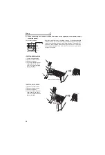
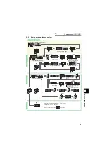
FR-F740-00310 or more
1) Remove the upper screws.
2) Remove the lower screws.
3) Pull the jumper toward you to
remove.
4) Connect the separate power supply
cable for the control circuit to the
upper terminals (R1/L11, S1/L21).
Never connect the power cable to
the terminals in the lower stand.
Doing so will damage the inverter.
CAUTION
1.
Do not turn off the control power (terminals R1/L11 and S1/L21) with the main circuit power (R/L1, S/L2, T/L3) on. Doing so
may damage the inverter.
2.
Be sure to use the inverter with the jumpers across terminals R/L1-R1/L11 and S/L2-S1/L21 removed when supplying power
from other sources. The inverter may be damaged if you do not remove the jumper.
3.
The voltage should be the same as that of the main control circuit when the control circuit power is supplied from other than the primary
side of the MC.
4.
The power capacity is 60VA or more for 00380 or less, 80VA or more for 00470 or more when separate power is supplied from R1/L11,
S1/L21.
5.
When the power supply used with the control circuit is different from the one used with the main circuit, make up a circuit
which will switch off the main circuit power supply terminals R/L1, S/L2, T/L3 when the control circuit power supply terminals
R1/L11, S1/L21 are switched off.
S1/L21
R1/L11
3)
4)
1)
2)
Power supply
terminal block for
the control circuit
Power supply terminal block
for the control circuit
R/L1S/L2 T/L3
R1/
L11
S1/
L21 Power supply
terminal block
for the control circuit
Main power supply
MC
V
U
W
00310,00380
00470,00620
00770 or more
Summary of Contents for FR-F 700 EC
Page 2: ......
Page 142: ...MEMO ...


