


6
Installation of the inverter and instructions
2.3 Installation of the inverter and instructions
•
Installation of the Inverter
•
Install the inverter under the following conditions.
•
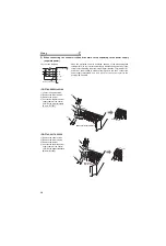
The inverter consists of precision mechanical and electronic parts. Never install or handle it in any of the following
conditions as doing so could cause an operation fault or failure.
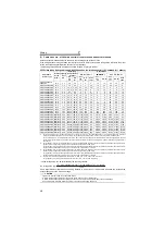
Installation on the enclosure
00620 or less
00770 or more
REMARKS
For replacing the cooling fan of the 04320 or more, 30cm of space is necessary in front of the inverter.
Refer to
page 84
for fan replacement.
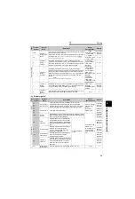
CAUTION
⋅
When encasing multiple inverters, install them in
parallel as a cooling measure.
⋅
Install the inverter vertically.
Refer to the clearances below
.
Vertical
Fix six positions for the FR-F740-
04320 to 08660 and fix eight positions
for the FR-F740-09620 to 12120.
Clearances
Ambient temperature and humidity
Measurement
position
Measurement
position
Inverter
Leave enough clearances and take
cooling measures.
Humidity: 90% RH maximum
01160 or less
01800 or more
5cm
5cm
5cm
10cm or more
10cm or more
5cm
or more *
5cm
or more *
10cm
or more
10cm
or more
20cm or more
20cm or more
Temperature: -10°C to 50°C (LD)
-10°C to 40°C (SLD*)
* Initial setting
(front)
*1cm or more for 00083 or less
Clearances (side)
Inverter
5cm
or more
Direct sunlight
High temperature,
high humidity
Horizontal placement
Mounting to
combustible material
Oil mist, flammable
gas, corrosive gas,
fluff, dust, etc.
Transportation by
holding the front cover
Vertical mounting
(When installing two or
more inverters, install
them in parallel.)
Vibration(5.9m/s
2
or more*)
* 2.9m/s
2
or more for the
04320 or more
Summary of Contents for FR-F 700 EC
Page 2: ......
Page 142: ...MEMO ...


