background image

English-12

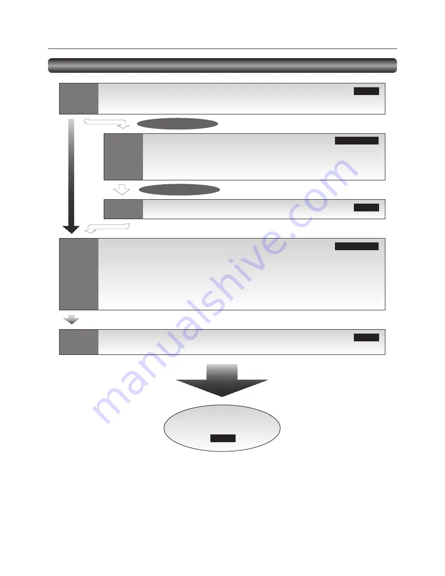
Flow of preparation

P-1

Preparation for installation

- Determine the installation location

- Ventilation requirements for enclosure mounting

 Page 13

Carry out as necessary

P-2

P-3

P-4

P-5

Carry out as necessary

Installing the speakers

Installing the monitor

- Installing and removing the stands (The stands are optionally available.)

- Installing the main switch cover

- Using the wall mount or ceiling mount

- Installing in the portrait position

 Pages 14 to 15

 Page 16

 Pages 17 to 21

 Page 22

 Page 23

Connection procedure

- Wiring diagram

- Prevention of disconnection of HDMI cable

- Connecting with a computer (analog connection)

- Connecting with a computer (digital connection)

- Connecting a video device (component video/HDMI device)

- Connecting a video device (composite video/S video device)/stereo amplifi er

Connecting the power cord to the monitor

- Connecting the power source

The monitor is ready for use.

How to Use

Preparation for use

Summary of Contents for BR931

Page 1: ...42 LCD Display Monitor MODEL ...

Page 2: ...omponent video HDMI device English 20 Connecting a video device composite video S video device stereo amplifier English 21 P 5 Connecting the power cord to the monitor English 22 Connecting the power source English 22 How to Use English 23 Flow of How to Using English 23 U 1 Turning on all the connected devices English 24 Turning on external devices English 24 Turning on the monitor English 24 Pow...

Page 3: ...plications Programmable Scheduling Function Page 38 The monitor s operating schedule can be programmed for up to seven different scheduled time intervals by time day of the week and input port This allows video content from different inputs to be displayed on certain monitors within the same installation according to the schedule and extends the monitor s life and saves the power by turning it off...

Page 4: ...terfere with radio and television reception 1 The power supply cord you use must have been approved by and comply with the safety standards of U S A 2 Please use the supplied shielded video signal cable Use of other cables and adapters may cause interference with radio and television reception 2 This equipment has been tested and found to comply with the limits for a Class B digital device pursuan...

Page 5: ...ERVICEABLE PARTS INSIDE REFER SERVICING TO QUALIFIED SERVICE PERSONNEL This symbol warns user that uninsulated voltage within the unit may have sufficient magnitude to cause electric shock Therefore it is dangerous to make any kind of contact with any part inside this unit This symbol alerts the user that important literature concerning the operation and maintenance of this unit has been included ...

Page 6: ...can be recycled and or reused This symbol means that electrical and electronic equipment batteries and accumulators at their end of life should be disposed of separately from your household waste If a chemical symbol is printed beneath the symbol shown above this chemical symbol means that the battery or accumulator contains a heavy metal at a certain concentration This will be indicated as follow...

Page 7: ...crystal leaks out do not inhale or swallow it Allow adequate ventilation around the monitor so that heat can properly dissipate Do not block ventilated openings or place the monitor near a radiator or other heat sources Do not put anything on top of the monitor The power cable connector is the primary means of detaching the system from the power supply The monitor should be installed close to a po...

Page 8: ... with the following For the use in the other regions use a power cord that matches the AC voltage of the power outlet and has been approved by and complies with the safety standard of those regions or countries The following components are supplied as option External Speakers Stands Screw M4x8 x 2 For Clamper Clamper x 2 For securing the power cord and HDMI cable LCD Monitor Power Cord For North A...

Page 9: ...back to the previous OSD menu Reference Control Lock mode You can lock the operation buttons See page 42 1 Main Power Switch Switches the main power on off 2 Remote control sensor and Power indicator Remote control sensor Receives the signal from the wireless remote control Power indicator Indicates the state of the LCD monitor Steady green The power is on Steady red The power is off Some operatio...

Page 10: ...NC connector Connectors and Terminals L IN IN OUT OUT R R B G Cr Pr Cb Pb Y H V 6 RS 232C connector D SUB 9 pin IN connector Connects with the RS 232C OUT connector of a computer or other connected LDT422V OUT connector Connects with the RS 232C IN connector of other connected LDT422V 7 RGB1 IN HDMI Connects with the digital video output of a computer DVD player etc 8 RGB OUT MINI D SUB 15 pin Out...

Page 11: ...INPUT button Selects video to be displayed in the sub picture CHANGE button Changes the main picture with the sub picture Description PIP Picture in Picture The sub picture is displayed within the main picture POP Picture out Picture The sub picture is displayed to the bottom right of the main picture SIDE BY SIDE The main picture and the sub picture are displayed side by side NOTE When the screen...

Page 12: ...Parts Name and Functions continued Installing and removing the Wireless remote control batteries The wireless remote control is powered by 1 5 V AAA batteries How to install the batteries 1 Unlock and pull up the cover in the arrow s direction 2 Align the batteries according to the and indications inside the case 3 Replace the cover How to remove the batteries 1 Unlock and pull up the cover in the...

Page 13: ...ch cover Using the wall mount or ceiling mount Installing in the portrait position Pages 14 to 15 Page 16 Pages 17 to 21 Page 22 Page 23 Connection procedure Wiring diagram Prevention of disconnection of HDMI cable Connecting with a computer analog connection Connecting with a computer digital connection Connecting a video device component video HDMI device Connecting a video device composite vide...

Page 14: ...essen the probability of injury and damage it doesn t assure its effectiveness against any kind of earthquake or disaster Do not sleep where the monitor may topple over or fall in case of an earthquake or other disaster Before moving the monitor remove the rope that is securing the monitor Failure to do so may result in injury or breakdown of the monitor Screw holes Screw hook etc commercially ava...

Page 15: ...t be used or installed without the Tabletop Stand or other mounting accessory Failure to follow the correct mounting procedures can result in damage to the equipment or injury to the user or installer Product warranty does not cover damage caused by improper installation Failure to follow these recommendations can void your warranty Use M6 screws having a length 10 mm longer than the thickness of ...

Page 16: ...fe of the LCD backlight Operation Environment Temperature shall be limited as shown below Operation Environment Temperature 5 35 C 41 95 F Humidity 20 80 without condensation Place the monitor in the position shown below Do not place the monitor in landscape in any other manner than shown Optional speakers SP 422V can not be attached when the LCD monitor is installed in the portrait position How t...

Page 17: ...if the monitor falls Left speaker Right speaker Before connecting the signal cable to PC and Video Optional speakers can be installed Please refer to user s guide of the optional speakers for the detailed installation procedure How to install the optional speakers 1 Use the metal fittings and screws that are supplied with the option speakers 2 Connect the cord of the left speaker to the SPEAKER S ...

Page 18: ...D player HDMI BNC HD disk player HDMI VCR RCA Stereo amplifier External speakers Clamper Accessory Cable Holder Before making connections First turn off the power of all the connected equipment before making connections Refer to the user manual of each piece of equipment NOTE Please use the audio cable without resistance when the audio output terminal of the audio device and PC is stereo mini Jack...

Page 19: ... Images may not be displayed correctly depending on the video card or driver being used Analog connection Connection via RGB3 IN D SUB connector 1 Connect an RGB cable mini D SUB 15 pin mini D SUB 15 pin accessory to the RGB3 IN connector 2 Select RGB3 using the INPUT button on the monitor or the D SUB button on the wireless remote control Connection via RGB4 IN BNC R G B H V or R G B Csync RGB sy...

Page 20: ... the RGB1 IN connector 2 Select RGB1 using the INPUT button on the monitor or the HDMI button on the wireless remote control Connection via the RGB2 IN connector DVI D 1 Connect a DVI D cable commercially available to the RGB2 IN connector 2 Select RGB2 using the INPUT button on the monitor or the DVI D button on the wireless remote control Audio connection Connect an audio cable ø3 5 mm stereo mi...

Page 21: ...e DVD HD IN connector YPbPr or YCbCr on the monitor use a BNC cable BNC x 3 BNC x 3 and a BNC RCA adaptor commercially available or a signal cable BNC x 3 D connector Select DVD HD using the INPUT button on the monitor or the YPbPr button on the wireless remote control To make audio connection connect an RCA cable audio to the AUDIO IN2 connector or the AUDIO IN3 connector Select AUDIO2 or AUDIO3 ...

Page 22: ...n RCA cable audio cable Connect the connectors of the RCA cable audio correctly For connection to the VIDEO IN connector select VIDEO using the INPUT button on the monitor or the VIDEO button on the wireless remote control For connection to the S VIDEO IN connector select VIDEO S using the INPUT button on the monitor or the VIDEO S button on the wireless remote control When connecting a stereo amp...

Page 23: ...the prongs into the power outlet socket Loose connection may cause noise NOTE Please refer to Safety Precautions Maintenance Recommended Use in this manual for proper selection of the AC power cord P 5 Connecting the power cord to the monitor Use the clamper to secure the cable firmly Clamper Accessory Cable holder Power cord For EU Power cord For North America ...

Page 24: ...ge 26 Page 26 Page 27 Page 26 Page 27 Page 28 Pages 28 to 29 Pages 30 to 31 Turning on all the connected devices Selecting the video input Controlling the external devices RGB3 and RGB4 only Auto setup Selecting the picture mode Screen adjustment Picture adjustment Volume control Schedule setting Remote control How to Use ...

Page 25: ...icator is on 3 When the power indicator glows red press the POWER button on the monitor The power indicator turns green Power Management Function This function reduces the power consumption of the monitor when the keyboard or the mouse is not used for a fixed period even though the power of the monitor is on While this function is working the screen becomes dark and the power indicator glows green...

Page 26: ... RGB2 DVI D RGB3 D SUB RGB4 BNC DVD HD YPbPr VIDEO S VIDEO S and VIDEO VIDEO NOTE The CAT5 and DISPLAY PORT buttons don t work 2 Select using the INPUT button on the monitor When you press the INPUT button on the monitor the video input OSD menu is displayed and you can select the video input using the and buttons Selectable video inputs are RGB1 HDMI RGB2 DVI D RGB3 D SUB RGB4 BNC DVD HD VIDEO S ...

Page 27: ...lock clock phase white level and black level NOTE The auto setup works on RGB3 and RGB4 only U 5 Selecting the picture mode Using the PICTURE MODE button on the wireless remote control you can select the picture mode suitable for images to be displayed HIGHBRIGHT The brightness is maximized STANDARD Factory default setting sRGB Suitable for color matching with sRGB compliant devices CINEMA Suitabl...

Page 28: ...ntal resolution vertical resolution and input resolution NOTE The position adjustment works on RGB3 RGB4 DVD HD VIDEO S and VIDEO only The clock adjustment and the resolution adjustment work on RGB3 and RGB4 only The zoom adjustment works on all video inputs U 7 Picture adjustment You can adjust the picture by pressing the MENU button on the wireless remote control or the control buttons on the bo...

Page 29: ...bottom of the monitor to display the OSD menu Using the AUDIO settings in the OSD menu you can adjust the balance treble and bass U 9 Schedule setting Carry out as necessary You can program the power on off and input selection using the SCHEDULE setting in the OSD menu that is displayed by pressing the MENU button on the wireless remote control or the control buttons on the bottom of the monitor U...

Page 30: ... time enter INPUT Set the video input to be selected when the power is turned on If you want to select the vide input that was selected before the power is turned on enter EVERY DAY Select this option to execute the schedule every day When you select EVERY DAY you cannot select any days of the week and EVERY WEEK MON SUN Select the days of the week on which you want to execute the schedule Unless ...

Page 31: ...tails 1 Interface PROTOCOL RS 232C BAUD RATE 9600 bps DATA LENGTH 8 bit PARITY BIT NONE STOP BIT 1 bit FLOW CONTROL NONE This LCD monitor uses RXD TXD and GND lines for RS 232C control Use RS 232C cables of reverse type commercially available 2 Control command diagram The command is structured by the address code function code data code and end code The length of the command is different for each ...

Page 32: ...PUT VIDEO _v1 5Fh 76h 31h INPUT DVD HD _v2 5Fh 76h 32h INPUT S VIDEO _v3 5Fh 76h 33h After sending the POWER ON or POWER OFF command wait for at least 1 minute to send the next command After sending any of the video input selection commands wait for at least 10 seconds to send the next command 5 Read command The computer sends the command without datacode to the monitor After receiving this comman...

Page 33: ...ed out Sub menu screen When you select a sub menu an OSD screen is displayed Sub menus contain information screens adjustment menu screens and selection menu screens as shown below Sub menu screen Picture reset for example Page 34 Page 35 Page 36 Page 37 Page 38 Page 39 Page 40 Page 41 Configuration of OSD screen This monitor is equipped with the OSD On Screen Display function for easy screen adju...

Page 34: ...n Select a sub menu by pressing the or button Accept the selected sub menu by pressing the SET button Accept the selected sub menu by pressing the INPUT button Select the setting value by pressing the or button and then press the SET button to accept the setting Select the setting value by pressing the or button and then press the INPUT button to accept the setting The OSD screen disappears when y...

Page 35: ...MINUS button to shift the selected color to the left around the color circle COLOR For the RGB1 DVD HD VIDEO S and VIDEO inputs only When you select COLOR by pressing the SET button on the wireless remote control the COLOR screen appears and you can adjust the following COLOR You can adjust all the colors at the same time Press the PLUS button to deepen the colors Press the MINUS button to lighten...

Page 36: ...screen center and the screen edges CUSTOM You can stretch the image horizontally and vertically as you desire using the CUSTOM ZOOM setting REAL The image is displayed without being stretched or reduced NOTE In the DYNAMIC mode the top and the bottom of the image may be cropped Full HD images are displayed as in the FULL mode CUSTOM ZOOM CUSTOM ZOOM becomes selectable when you set ZOOM MODE to CUS...

Page 37: ...decrease the right volume TREBLE You can adjust the high frequency sound Press the PLUS button to increase the treble sound Press the MINUS button to decrease the treble sound BASS You can adjust the low frequency sound Press the PLUS button to increase the bass sound Press the MINUS button to decrease the bass sound AUDIO RESET You can reset all the AUDIO settings to the factory defaults ...

Page 38: ... is output PIP H POSITION You can adjust the horizontal position of the sub screen Press the PLUS button to move the sub screen to the right Press the MINUS button to move the sub screen to the left PIP V POSITION You can adjust the vertical position of the sub screen Press the PLUS button to move the sub screen up Press the MINUS button to move the sub screen down SUB INPUT You can select the vid...

Page 39: ...in the particular schedule Use the and buttons to increase the time and select the input port The SET button is used to make a selection If you create a schedule but do not want to set the power on time select in the ON time slot If you do not want to use a power off time select in the OFF time slot If there is no input selected showing in the input spot the input from the previous schedule will b...

Page 40: ...o divide the displayed image into up to 5 pieces horizontally and vertically NOTE It is required to connect the same video signal to each monitor via a distributor or RGB OUT When TILING is activated PIP POP SBS and STILL are disabled TILING doesn t work in the REAL picture size mode H MONITORS Select the number of images obtained by horizontal division V MONITORS Select the number of images obtai...

Page 41: ...d on the screen SCREEN SAVER You can set the SCREEN SAVER functions to reduce the risk of image persistence GAMMA When you select ON the gamma mode where image persistence is difficult to occur is used COOLING FAN When you select ON the cooling fan always runs When you select AUTO the built in fan automatically starts running according to the operating temperature BRIGHTNESS When you select ON the...

Page 42: ...lace signals are converted into progressive signals Select this setting for normal cases INTERLACE Interlace signals are displayed without being converted Though this setting is suitable for motion images still images aren t displayed properly COLOR SYSTEM For the VIDEO S and VIDEO inputs only You can select the color system depending on the video device you use AUTO NTSC PAL SECAM PAL60 or 4 43 N...

Page 43: ...YNAMIC NORMAL Squeeze signal NORMAL NORMAL FULL DVD HD VIDEO only Normal size of each signal Recommend picture size Audio input change RGB1 HDMI AUDIO1 AUDIO2 AUDIO3 Other inputs AUDIO1 AUDIO2 AUDIO3 OSD information RGB2 1024 x 768 48kHz 60Hz AUDIO 1 SIZE FULL DVD HD AUDIO 3 SIZE FULL VIDEO S NTSC AUDIO 3 SIZE NORMAL RGB2 1024 x 768 48kHz 60Hz AUDIO 1 VIDEO S NTSC SIZE FULL Control Lock mode You c...

Page 44: ...button on the wireless remote control you can change the PIP POP and SIDE BY SIDE modes in the order shown below Alternatively you can change the modes using the PIP MODE setting of PIP in the OSD main menu See page 37 Reference The resolutions in the PIP and POP modes are as follows PIP SIZE SMALL 320 pixels X 240 pixels MIDDLE 480 pixels X 320 pixels LARGE 640 pixels X 480 pixels POP SIZE 450 pi...

Page 45: ... may need to be re adjusted Check the monitor and your display card with respect to the compatibility and recommended signal timings If the displayed text is garbled change the video mode to the non interlace mode and use 60 Hz refresh rate Image of component signal is greenish Check to see if the DVD HD input connector is selected LED on the monitor is not lit No green or red color can be seen Po...

Page 46: ...te BNC Supported Resolution Composite Separate NTSC PAL SECAM 4 43 NTSC PAL60 Component Digital 480i 480p 576i 576p 1080i 720p 1080p Audio Input Output Input Connector Analog RCA pin jack L R x 2 Stereo mini jack Digital HDMI digital audio Output Connector RCA pin jack Speaker Audio Output External Speaker jack 7W 7W 8 ohm Control Input Output Input Connector RS 232C D SUB 9 pin Output Connector R...

Page 47: ...7 DDC CEC Ground 4 TMDS Data1 11 TMDS Clock Shield 18 5V Power 5 TMDS Data1 Shield 12 TMDS Clock 19 Hot Plug Detect 6 TMDS Data1 13 CEC 7 TMDS Data0 14 Reserved N C on device 3 Digital RGB input DVI D RGB2 Pin Assignment of DVI D connector 1 TMDS Data2 9 TMDS Data1 17 TMDS Data0 2 TMDS Data2 10 TMDS Data1 18 TMDS Data0 3 TMDS Data2 Shield 11 TMDS Data1 Shield 19 TMDS Data0 Shield 4 NC 12 NC 20 NC ...

Reviews: