background image


MITSUBISHI ELECTRIC 9900CX SERIES UPS


9900CX SERIES UPS 

OWNERS / TECHNICAL MANUAL


Page Number:

1-10

B) Bypass 

Operation: 

Load Power supplied through UPS internal static bypass line.


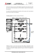
Figure 1.2 


Single Line Diagram - Bypass Operation: Load fed through static bypass line 


Referring to Figure 1.2: The Internal Bypass line is a Hard-wired line through 52S which 

supplies the critical load with unconditioned bypass input power. Upon switching to the Internal 

Bypass line, the Static Transfer Switch line through CB3 (herein after STS contactor CB3) 

supplies the power immediately, and then the Internal Bypass line through 52S supplies the 

power. In the event of a switching to the Bypass line, the power to the critical load will be 

uninterrupted. The purpose of this Internal Bypass line is to route power to the critical load while 

the UPS module is de-energized (converter and inverter), and during Start-up before the system 

is fully operational. 


Each UPS internal static bypass line will equally share the power supplied to the critical load in 

the Parallel Operation if a cable length of bypass line is equal each other. For a MMS unable to 

equalize the cable length, additional rectors should be installed to compensate the difference in 

cable impedance. 

Bypass Module

CB3

CONVERTER / INVERTER

CHARGER

52C

Static Transfer 

Switch

52S

CB1

CB2

UPS Module

CONVERTER / INVERTER

CHARGER

52C

CB1

CB2

UPS Module

AC

input

Bypass

Input

CB

User 

supplied

MCCB 

User 

supplied

MCCB 

CB

Power Flow

Not in Use

Output

Battery 

Cabinet 
External

BATTERY

CB

CONVERTER / INVERTER

CHARGER

52C

CB1

CB2

UPS Module

UPS 

CABINET

~ ~

3

6 UPS 

Modules

Summary of Contents for 9900C Series

Page 1: ...UNINTERRUPTIBLE POWER SUPPLY SYSTEM MODEL 9900CX SERIES OWNER S TECHNICAL MANUAL Inclusive Parallel Operation System Application UNINTERRUPTED Peace of Mind U ENM00043 REV 0 ...

Page 2: ...Preface Revision A 04 04 2017 4GBA0114 ...

Page 3: ...CATIONS 1 15 2 0 OPERATION CONTROLS AND INDICATORS 2 1 2 1 LED DISPLAY 2 2 2 2 EPO BUTTON 2 2 2 3 LIQUID CRYSTAL DISPLAY 2 3 2 4 EXTERNAL SIGNAL TERMINAL BLOCK 2 8 2 5 EXTERNAL COMMUNICATION CONNECTOR 2 15 3 0 INSTALLATION AND OPERATION 3 1 3 1 TRANSPORTATION AND INSTALLATION 3 1 3 2 INSTALLATION PROCEDURE 3 1 3 3 PROCEDURE FOR CABLE CONNECTIONS 3 2 3 4 OPERATING PROCEDURES 3 8 4 0 RESPONSE TO UPS...

Page 4: ...ifications 1 16 Table 1 6 Rating of Contactors Breakers and Fuses 1 17 Table 2 1 Selectable Items for Output Contacts 2 11 Table 2 2 Selectable Items for Input Contacts 2 14 Table 3 1 How to Transport and Install the System 3 1 Table 3 2 List of UPS Weights 3 1 Table 3 3 Maximum Permitted Fault Current 3 2 Table 3 4 Recommended Cable Sizes 3 4 Table 3 5 Recommended Hardware 3 4 Table 3 6 Crimp Typ...

Page 5: ...2 5 Remote Local Operation or Date Time Adjustment Select 2 5 Figure 2 6 a Log Menu 2 5 Figure 2 6 b Event Log 2 5 Figure 2 6 c Battery Log 2 5 Figure 2 7 a Main Screen Battery Operation 2 6 Figure 2 7 b Measurement Screen Battery Operation 2 6 Figure 2 8 Main Screen Fault Indication 2 7 Figure 2 9 Message Screen 2 7 Figure 2 10 a External Signal Terminal Block TN21 25 NEC Class2 2 8 Figure 2 10 b...

Page 6: ...anual Warning A warning notice icon conveys information provided to protect the user and service personnel against hazards and or possible equipment damage Caution A caution notice icon conveys information provided to protect the user and service personnel against possible equipment damage Note A Note notice icon indicates when the user should make a reference of information regarding the UPS oper...

Page 7: ...ontains descriptions required to operate the UPS Please read this manual carefully and retain it for future reference This manual contains important instructions for the 9900CX SERIES Uninterruptible Power Supply System that should be followed during installation and maintenance of the UPS and batteries Lethal voltages exist within the equipment during operation Observe all warning and cautions in...

Page 8: ...of the UPS will rise and consequently a fire may be caused due to liquid leakage from batteries short circuits or parts deterioration PRECAUTIONS FOR WIRING CAUTION Ask professional agents for wiring work Inappropriate wiring work may cause electric shocks injuries or fire PRECAUTIONS TO PROFESSIONAL AGENTS CAUTION Use wiring conduit pits or racks for input output wiring Inadvertent wiring may cau...

Page 9: ...ts or oil Keep the battery away from flexible vinyl materials g Since the electric energy remains in the used batteries treat them carefully to prevent sparks and short circuits APPLICATION CAUTION If the UPS System is to be applied to support equipment that could affect human safety the following steps must be adhered to 1 Consult with Mitsubishi Electric Power Products Inc UPS Division 2 Special...

Page 10: ...in the range 41 F 5 C to 95 F 35 C 3 Relative humidity The relative humidity must be held between 5 and 95 There must be no condensation due to temperature changes 4 Altitude This equipment must not be applied at altitude that exceeds 1980m 6500ft above sea level 5 Dust Dust in the room where the UPS is installed must not exceed normal atmospheric dust levels In particular that dust should not inc...

Page 11: ...ons are as follows Table 1 2 Rating of Bypass Input Circuit Breaker Capacity kVA Bypass Voltage Vac Bypass Rating Aac Breaker A 1050 480 1263 1600 1400 480 1684 2500 1750 480 2105 3000 2100 480 2526 4000 AC input and AC output overcurrent protection and disconnect devices shall be field supplied and installed The DC circuit breaker MCCB shall be field supplied and installed The overcurrent protect...

Page 12: ...ad for the specified battery time If the input power is not restored promptly backup power from the UPS battery permits the orderly shutdown of equipment supported by the UPS The UPS is simple to start up operate and maintain The 9900CX SERIES UPS is available in 1050 1400 1750 and 2100 kVA Specifications are shown in Section 1 5 This manual provides an overview of the 9900CX SERIES components and...

Page 13: ...nvert input AC power to output AC power required by the critical load CHARGER The UPS components which contain the equipment and controls necessary to regulate DC power required for battery charging and for supplying power to the Inverter BYPASS MODULE The metal enclosure which contains the Bypass line the Static transfer switch UPS operator controls and internal control systems BYPASS LINE The li...

Page 14: ...PS inverters is used to power the load Referring to Figure 1 1 Input AC power is converted to DC by the Converter DC power is utilized to charge the UPS battery and to provide power to the Inverter The Inverter converts the DC power to clean AC power to supply the critical load The conversion inversion process eliminates any voltage transients or fluctuations existing in the input power before it ...

Page 15: ...d between all UPS whenever the system is in the Parallel Operation In the event of a UPS module failure during Parallel Operation the critical load power will be continually supplied and shared by all other UPS The Bypass Input circuit breaker MCCB for protection of the UPS and cables are field supplied and field installed See WARNING 4 on page 1 4 ...

Page 16: ...itical load will be uninterrupted The purpose of this Internal Bypass line is to route power to the critical load while the UPS module is de energized converter and inverter and during Start up before the system is fully operational Each UPS internal static bypass line will equally share the power supplied to the critical load in the Parallel Operation if a cable length of bypass line is equal eac...

Page 17: ...by UPS battery Figure 1 3 Single Line Diagram Battery Operation Referring to Figure 1 3 In the event of AC input source failure or interruption the UPS Converter s will de energize and the UPS battery s will immediately discharge and supply DC power to the Inverter to maintain continuous AC power to the load This operation will continue until Bypass Module CB3 CONVERTER INVERTER CHARGER 52C Static...

Page 18: ...t a reduced load s In the case of the Parallel Operation When power is restored after a low battery shutdown the UPS converter s automatically restarts operation the charger s recharges the batteries and the Inverter s is automatically restarted without operator intervention Load is automatically assumed by the inverter without operator intervention s In the case of the Parallel Operation The powe...

Page 19: ...ECHNICAL MANUAL Page Number 1 13 Figure 1 4 UPS Parts Location 1 UPS cabinet Front View 2 Backside of Bypass Module door UPS Module Cable Entry Section Bypass Module LCD Touch Panel Monitor Display LCD Touch Panel Monitor Display Display PCB DPAU 89 Main PCB UPJR D ...

Page 20: ...SERIES UPS 9900CX SERIES UPS OWNERS TECHNICAL MANUAL Page Number 1 14 3 UPS cabinet Front Inside View External I F PCB IOAU 19 CB2 CB1 left 52C right Back Side of PCB Unit 52S CB3 DC INPUT DC INPUT AC INPUT BYPASS INPUT AC OUTPUT ...

Page 21: ...oltage 3 phase 3 wire Output voltage 3 phase 3 wire 1050kVA 1000kW 480V 480V 480V 1400kVA 1330kW 480V 480V 480V 1750kVA 1660kW 480V 480V 480V 2100kVA 2000kW 480V 480V 480V Table 1 4 UPS Cabinet Information UPS kVA Cable Entry Width in mm Depth in mm Height in mm Weight lb kg Heat Loss kBTU h 1050 BOTTOM TOP 118 2 3003 2 35 5 901 6 80 7 2048 6 6283 2850 127 6 1400 BOTTOM TOP 167 3 4250 35 5 901 6 8...

Page 22: ...tability 0 01 in free running mode Power Factor 0 95 Power Factor Range 0 7 lagging to 0 8 leading Voltage THD 2 maximum THD at 100 Linear Load 5 maximum THD at 100 non linear load Transient Response 2 maximum at 100 load step 1 maximum at loss return of AC power 5 maximum at load transfer to from static bypass Transient Recovery Less than 20ms Voltage Unbalance 2 maximum at 100 unbalanced load Ph...

Page 23: ...S Bypass contactor 1278A 1992A 2843A 88RC Control circuit contactor 20A Breakers User supply Battery disconnect breaker Recommended 3000A 4000A 5000A 6000A User supply AC input breaker Recommended 1600A 2500A 3000A 4000A User supply Bypass input breaker Recommended 1600A 2500A 3000A 4000A FP FC FN DC fuse 315A 690V FBP FBN DC fuse 1000A 690V FBR1 FBR2 FBR3 FBR FBS FBT FBO1 FBO2 FBO3 Control power ...

Page 24: ...ES UPS OWNERS TECHNICAL MANUAL Page Number 2 1 C 2 0 OPERATOR CONTROLS AND INDICATORS The 9900CX Series operator controls and indicators are located as follows Bypass Module door exterior Figure 2 1 Operation Display Panel Front panel 8 3 2 1 7 4 5 6 ...

Page 25: ...en power is supplied to load devices by static bypass Indicates the state of bypass transfer switch 52S 4 Overload OVERLOAD yellow Illuminates in overload condition 5 LCD fault LCD FAULT red Illuminates when an error occurs 6 UPS fault UPS FAULT red Annunciator intermittent or constant tones Illuminates when an error occurs in the system In this case the details of the error are indicated on the d...

Page 26: ...t stop function The LCD panel also allows the user to verify the status and operation of the UPS Module Figure 2 2 Main Screen The following will be displayed when the START STOP key on the MAIN MENU is pressed Jump into OPERATION MENU 1 Start Stop Operation Figure 2 3 The display indicates the Start Stop operation for the UPS system If this operation is PIN protected the user is required to enter...

Page 27: ...put Transfer from Bypass Line to Inverter STOP Output Transfer from Inverter to Bypass Line Figure 2 3 b Start Operation Figure 2 3 c Stop Operation Follow Start Stop operation guidance accordingly B MEASUREMENT MENU Figure 2 4 This screen shows details of measured values Input and Output values are displayed During Battery operation Remaining battery power and Run time are also displayed Figure 2...

Page 28: ...y will appear when battery equalizing charge is set up Setup is based on battery type Figure 2 5 Remote Local Operation or Date Time Adjustment Select D LOG MENU Figure 2 6 This LOG MENU displays two Touch icons in EVENT LOG and BATTERY LOG Pressing the EVENT LOG icon up to 100 condition operation records will be displayed Press or button for page turning Pressing the BATTERY LOG icon Number of ba...

Page 29: ...n Figure 2 7 b Measurement Screen Battery Operation The LCD will display a battery low voltage message when the battery capacity is near depletion The End of Battery Discharge announcement is displayed when the battery end voltage is reached At this time the inverter will perform an electronic shutdown to prevent battery loss of life from extreme deep discharge conditions When the input power is r...

Page 30: ...in menu is pressed 1 MESSAGE Figure 2 9 The display shows a fault code the description of the fault and a guidance of what action is to be taken by the user A maximum of 10 faults is displayed at one time If an input power failure occurs during a fault condition the fault indication and input power failure announcement are alternatively displayed at 5 second intervals Figure 2 9 Message screen 2 S...

Page 31: ...t output port presented OUT1 to OUT8 are user programmable but are factory default set being also shown in Figure 2 10 Adding same external I F PCB IOAU 19 doubling signal outputs is applicable for OUT1 to OUT8 Figure 2 10 a External Signal Terminal Block TN21 25 NEC Class2 TN21 25 Summary Alarm OUT2 LOAD ON INVERTER OUT3 BATTERY OPERATION OUT4 CONVERTER OPERATION OUT5 BATTERY LOW VOLTAGE OUT6 OVE...

Page 32: ... 10 b External Signal Terminal Block TN11 14 NEC Class2 TN11 14 User supplied dry contact IN3 BATTERY TEMP HIGH IN1 REMOTE INVERTER START IN2 REMOTE INVERTER STOP REMOTE EPO IN4 POWER DEMAND CB2 AX 52L AX 21 23 25 27 29 35 33 31 22 24 26 28 30 36 34 32 Battery Breaker Panel Load Circuit Switch Not use UPS ...

Page 33: ... 4 Load on Bypass contact OUT1 Activated when the power is supplied from the static bypass input Terminals 5 to 6 Load on Inverter contact OUT2 Activated when the power is supplied by the inverter Terminals 7 to 8 Battery Operation contact OUT3 Activated when the battery is operating following an AC power failure Terminals 9 to 10 Converter Operation contact OUT4 Activated when the converter is op...

Page 34: ...MAL 5 BYPASS ABNORMAL 6 BATTERY ABNORMAL 7 BATTERY LOW VOL 1 8 BATTERY LOW VOL 2 OUT5 9 BATTERY DEPLETION 10 OVERLOAD OUT6 11 OVERLOAD PREALARM 12 FAULT GROUP 1 13 FAULT GROUP 2 14 BYPS SYNCHRONOUS 15 BYPS ASYNCHRONOUS 16 REMOTE OPE ENABLE 17 LOAD ON INVERTER OUT2 18 LOAD ON BYPASS OUT1 19 LOAD ON AC 20 BATTERY OPERATION OUT3 21 CONVERTER OPERATION OUT4 22 INVERTER OPERATION 23 CB1 CLOSE 24 CB2 CL...

Page 35: ...pply voltages to remote access input terminals Damage to UPS may result Refer to Figure 2 12 for a typical wiring configuration Although this figure applies to the remote start stop terminals the same wiring arrangement is used for emergency stop power demand and battery temperature high Figure 2 12 Remote Start Contact Connections Start Relay Coil current 16 7mA Use Momentary Switches Only UPS Ca...

Page 36: ... be programmed for remote operation Refer to Operations Menu for procedure Terminals 29 to 30 Battery Temp High contact input IN3 Input fed by a thermocouple that monitors battery temperature The converter float voltage level is reduced for battery over temperature conditions External thermocouple is user supplied Terminals 31 to 32 Power Demand Command contact input IN4 This contact is used to co...

Page 37: ...Y TEMP ABNORMAL IN3 7 GENERATOR OPERATION 8 ASYNCHRONOUS 9 ANOTHER BUS SYNC 10 REMOTE INVERTER MMS 11 REMOTE BYPASS MMS 12 EXT BYP dV STR 13 USE IB LIMIT 2 14 CHARGER STOP 15 EXTERNAL ALARM 16 CB2 EX 17 CHARGE DEVICE ERR 18 CONVERTER OPE PROHIBITION 19 REMOTE MOD START 20 REMOTE MOD STOP 21 SPARE 21 22 SPARE 22 23 SPARE 23 24 SPARE 24 25 SPARE 25 26 SPARE 26 27 SPARE 27 28 SPARE 28 29 SPARE 29 30 ...

Page 38: ...ector is shown in Figure 2 13 Figure 2 13 External Communication Connector NEC Class2 Pin 1 Not used Pin 2 RXD Receive data Pin 3 TXD Transmit data Pin 4 Not used Pin 5 GND Signal ground Pin 6 Not used Pin 7 Not used Pin 8 Not used Pin 9 Not used Consult MITSUBISHI ELECTRIC POWER PRODUCTS INC for details on DiamondLink monitoring software and its capabilities D SUB 9Pin male PCB IOAU 19 1 2 3 4 5 ...

Page 39: ...ing CAUTION Floor shall be flat and level 3 inches surrounding mounting holes shall be flush with maintenance pad or floor 3 2 INSTALLATION PROCEDURE A Note the load tolerance of the floor Refer to Table 3 2 for list of UPS weights Table 3 2 List of UPS Weights UPS Capacity kVA 1050 1400 1750 2100 Weight lb 6283 9580 11770 13530 B Minimum clearance required for ventilation Right side 25 mm 1 inch ...

Page 40: ...2100 480 25 000 3 3 PROCEDURE FOR CABLE CONNECTIONS 1 Identify the input output power terminal blocks as shown in Figure 3 1 2 Connect the internal control wire and power wire 1 Control wire interconnections 1 Battery CB ON Auxiliary to terminal TN11 14 21 22 of external I F PCB IOAU 19 2 Power wire AC input Bypass input AC output interconnections a From user s distribution panel 1 X1 A phase to A...

Page 41: ... as desired Refer to section 2 4 and Figure 2 10 for functional description 2mm 2 or less shielded conductor is recommended 5 One 1 source feeding the UPS 1 Confirm that an external input circuit breaker sized to protect both the AC input and the bypass line is installed Refer to equipment nameplate for current ratings Connect the bypass input power cables from the input service entrance to the by...

Page 42: ...80V 480V 7 x 500MCM 347 469 in lbs 7 x 500MCM 347 469 in lbs 7 x 500MCM 347 469 in lbs 12 x 500MCM 347 469 in lbs 2100kVA 480V 480V 9 x 500MCM 347 469 in lbs 9 x 500MCM 347 469 in lbs 9 x 500MCM 347 469 in lbs 14 x 500MCM 347 469 in lbs 1 Use 75 degree C copper wire 2 The cables must be selected to be equal or larger to the sizes listed in the table 3 Voltage drop across power cables not to exceed...

Page 43: ...SCO BURNDY YA36 CRA 600L YA39 LB GREEN GREEN 22 472 22 472 1030 750 MCM B BURNDY ILSCO YA39 CRA 750L BLACK BLACK 24 24 NOTE When using crimp type lugs the lugs should be crimped to the specifications given in the manufacturer s instructions for both crimp tool and lug Figure 3 1 UPS Terminal Designation Bypass Module CB3 CONVERTER INVERTER CHARGER 52C Static Transfer Switch 52S CB1 CB2 UPS Module ...

Page 44: ...insulating distance The wiring also should fix to the frame to ensure the insulating distance satisfied the condition 2 3x 2 holes bases 3 4x 4 holse bases 3 UPS cabinet Front View Cable Entry Section Left Side View Location of bus bars and terminal blocks Bottom Top Entry DC Input For power terminals use 1 2 12mm diameter bolts 35 5 901 6 Grounding Bar E External signal line access 1 3 2 3 2 2 DC...

Page 45: ...ure 3 3 Diagram of Power Wire Control Wire Interconnections between UPS and Battery External signal terminal IOAU 19 TN1 UPS module Wall mounted DC breaker for Battery Auxiliary DC circuit breaker Negative User supplied User supplied BP BN 22 21 Power terminal Positive Page Number 3 7 ...

Page 46: ...ker for each unit is closed user supplied If a dual source is feeding the UPS close the External AC Input Circuit Breaker user supplied manually also b Close Battery Disconnect Circuit Breaker user supplied c The LCD panel boots up automatically and the screen will show that the Load is powered by bypass line d On the LCD panel select OPERATION tab and then press the START OPERATION button to proc...

Page 47: ...ct LOCAL ONLY or REMOTE LOCAL in the OPERATION MENU d Open the Battery Disconnect circuit breaker user supplied manually WARNING Verify the load is OFF if the next step is to be performed NOTE Power to the critical load is supplied through the bypass line Power to the critical load will be lost after execution of the next step The load will drop e If a dual source is feeding the UPS open the Exter...

Page 48: ...erify that Critical Load Cabinet CLC Circuit Breaker SMB is closed 2 Verify that CLC System Output Circuit Breaker 52L is open 3 Verify that CLC UPS Circuit Breakers 52L1 52L2 and 52Ln are closed Start up from UPS 1 to UPS n 1 Start up each UPS in accordance with A Start Operation Each UPS will start Inverter Operation in synchronization with the bypass input Meaning of the icons in Figure 2 3 a i...

Page 49: ...When faults happen contact the Authorized Mitsubishi Electric Service Representatives or call Mitsubishi Electric at 1 800 887 7830 NOTE The error code indicated on the LCD display panel when an UPS alarms is very important In order to reduce repair time please include this information along with the operation and load status for all correspondence to Mitsubishi Electric field service group UPS FA...

Page 50: ... equal to 80 of nominal capacity Replace battery if its capacity is within this percentage B UPS Component Parts UPS components have a defined life expectancy Fan Capacitors Air Filters etc Contact Mitsubishi Electric Power Products Inc or its authorized service representatives for a complete parts replacement schedule Recommended replacement time interval varies with operating environment Contact...

Page 51: ...r description and required action In the event of a fault occurring A Verify and record the occurrence of the alarm Note details of alarm message displayed on the LCD display panel Contact Mitsubishi Electric Power Products Inc at 1 800 887 7830 B If a circuit breaker MCCB has tripped depress the toggle to reset the breaker before closing it again ...

Page 52: ... sound Bypass Input Abnormal UA815 TRANSFER PROHIBITION Transfer to bypass is not available due to bypass abnormality Intermittent sound UA817 EMERG STOP ACTIV The emergency stop was activated by the EPO switch or an external contact Continuous sound UA821 REM BUTTON CLOSE Remote start signal is being received continuously for a considerable time Intermittent sound UA822 LOC BUTTON ABNL Local star...

Page 53: ...BATTERY LIQUID LOW Low level of battery electrolyte solution CHECK BATTERY Intermittent sound Battery abnormal UF161 CHG STOPPED UF151 failure is running for over 24 hours CALL SERVICE ENGINEER Intermittent sound Minor UF162 BATTERY ABNORMAL Failure detection based on battery self check CALL SERVICE ENGINEER Intermittent sound Minor UF163 BAT VOLTAGE ABNL All converter modules have detected batter...

Page 54: ...unication integrity error or No communication Individual Bypass CALL SERVICE ENGINEER Intermittent sound Minor UF340 MODULE MINOR FAULT A power converter module has detected major fault condition CALL SERVICE ENGINEER Continuous sound Major UF341 1 MAJOR FAULT Power converter module 1 has detected major fault condition CALL SERVICE ENGINEER Intermittent sound Minor UF342 2 MAJOR FAULT Power conver...

Page 55: ...Intermittent sound Minor UF383 CTRL CIRCUIT ERR Module overcurrent answer continued for 10 seconds or more CALL SERVICE ENGINEER Intermittent sound Minor UF384 CTRL CIRCUIT ERR Minor communication error by fall out of only A side of dual connector CALL SERVICE ENGINEER Intermittent sound Minor UF385 CTRL CIRCUIT ERR Minor communication error by fall out of only B side of dual connector CALL SERVIC...

Page 56: ...rnal contact Alarm MA824 CB2 OPEN The battery disconnect contactor CB2 open Alarm MA834 BATTERY DEPLETED The battery voltage has reached the depleted level Major End of Discharge MA836 INVERTER OVERLOAD The output load active power has exceeded 110 of the rated current Alarm Overload MA870 BALANCER OVERLOAD The UPS detected a neutral point voltage unbalance Alarm Overload MF001 I P CIRCUIT ABL Det...

Page 57: ...ajor MF202 INVERTER UV Output voltage dropped Major MF203 INVERTER OC Detection of inverter overcurrent Major MF204 O P CIRCUIT ABNL Detection of a large variation of the reference error signal current reference and actual current Major MF207 ZERO PHASE OC Inverter zero sequence overcurrent Major MF208 CTRL CIRCUIT ERR Cross current is abnormal Major MF210 52C ABNORMAL Error to open the contactor ...

Page 58: ...supply Major MF331 CTRL CIRCUIT ERR Cable disconnection in the main driver PCB Phase A Major MF332 CTRL CIRCUIT ERR Cable disconnection in the main driver PCB Phase B Major MF333 CTRL CIRCUIT ERR Cable disconnection in the main driver PCB Phase C Major MF334 CTRL CIRCUIT ERR Cable disconnection in the main driver PCB Chopper Major MF376 CTRL CIRCUIT ERR Logic signal abnormal Supply ON Minor MF552 ...

Page 59: ...gister your UPS for warranty purposes please complete the warranty registration form and fax it to the Mitsubishi Electric UPS Division Service Department fax line shown on the registration form Next page For warranty purposes it is essential that any and all service work that may be required on your Mitsubishi brand UPS equipment is performed by a Mitsubishi Electric Authorized Service Center The...

Page 60: ...ture Date Which ONE of These Best Describes Your Organization s Primary Business Classification Number of Employees at This Location is Energy Producer __ Utility __ Alternate Energy Manufacturing Co __ OEM __ Process __ Consumer Goods __ Electronics __ Power Quality Equipment __ Commercial Business __ Electrical Contractor __ Healthcare __ Internet __ Education Univ Service Service __ Consulting ...

Page 61: ......

Reviews: