


English –
21
English
The control unit has a number of optional functions to enable the user to
add specific functionalities to the automation, thus personalising the prod-
uct according to special needs.
10
– AUTOMATION OPERATION ADJUSTMENT
To personalise operation of the automation, a number of functions can be
enabled or disabled, also with the option for modifications to settings as
required. The functions are:
• AUTOMATIC LEAF CLOSURE
. When this function is enabled, at the
end of the Opening manoeuvre command by the user, the control unit
automatically closes the gate again after a set time interval.
• LEAF MOVEMENT SPEED
. This function enables entry of the required
speed of the automation implemented to move the gate leaf.
• AUTOMATION SENSITIVITY TO OBSTACLES
. During a manoeuvre, if
an obstacle accidentally stops gate leaf movement (a strong gust of wind,
a vehicle, person etc.) this function promptly detects the increase in motor
stress to contract the obstacle and activates immediate total inversion of
movement. If “automatic leaf closure” is set, the control unit re-attempts
the movement a second time and on the third time, after a brief inversion,
it stops the manoeuvre permanently.
• DECELERATION MODES
. This function enables selection of the decel-
eration start point during gate leaf travel both in the Closing and Opening
phases.
Note
– This parameter is essential for guaranteeing a low impact force in
the event of impact with an obstacle in the final phase of a manoeuvre.
The values of these functions can be set according to personal require-
ments using the following procedure with a transmitter that has at least
one key already memorised on the control unit.
Note
– During this procedure, each time a key is pressed the flashing light
emits one flash.
01.
Press and hold the keys “
T1
” and “
T2
” simultaneously on the trans-
mitter for at least
5 seconds
, after which release.
The two leds (green and red) on the Control unit flash to indicate entry
to function programming mode
(the leds continue to flash throughout
the procedure)
.
02.
Press and hold a transmitter key (already memorised on that of the
control unit) for at least
1 second
(the green Led emits one flash)
.
03.
Then select one of the four functions available and on the transmitter
press the key associated with the function for at least 1 second
(the
green Led emits one flash)
:
• Automatic leaf closure
= (press key “
T1
”)
• Leaf movement speed
= (press key “
T2
”)
• Leaf sensitivity to obstacles
= (press key “
T3
”)
• Leaf deceleration points
= (press key “
T4
”)
04.
Lastly, refer to
Table 3
, select the required value in correspondence
with the selected function and on the transmitter press the key asso-
ciated with the selected value for at least
1 second
(the green and
red Leds emit one confirmation flash)
.
Notes to
Table 3
:
– The Table states the values available for each of the 4 special functions
and the corresponding key to be pressed on the transmitter for selection
of the specific value.
– The factory settings are highlighted in grey.
(
*
) –
The “
High
” parameter means that the gate can detect obstacles that
generate a low force, such as a strong gust of wind.
–
The “
Low
” parameter means that the gate can detect obstacles that
generate a high force, such as a stationary car.
– In the event of a power failure, on restoral of power the first manoeuvre
command will be executed at low speed, regardless of the type of speed set.
11
– MEMORISING A NEW TRANSMITTER WITH
PROCEDURE IN THE VICINITY OF THE CONTROL
UNIT [with a transmitter already memorised]
A NEW transmitter can be memorised in the control unit memory without
acting directly on key
P1
of the control unit, but by simply working within
its reception range. To use this procedure, an OLD transmitter, previously
memorised and operative, is required. This enables memorisation of the
same function of a specific key on the OLD transmitter on any key of the
NEW transmitter.
Warnings:
– The procedure must be performed within the reception range of
the receiver (maximum 10-20 m from receiver).
–
The procedure memorises a single key of the new transmitter. To
memorise other keys, repeat the same procedure
01.
On the NEW transmitter, press and hold the key to be memorised for
at least
5 seconds
and then release.
02.
On the OLD transmitter, slowly press the control key to be memo-
rised on the other transmitter
3 times
.
03.
On the NEW transmitter, press the same key pressed in point 01
once
.
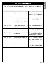
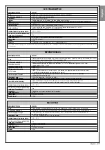
ADJUSTMENTS AND OTHER OPTIONAL FUNCTIONS
TABLE 3
AUTOMATIC LEAF CLOSURE
No closure —> (press key “
T1
”)
Closure after 15 seconds —> (press key “
T2
”)
Closure after 30 seconds —> (press key “
T3
”)
Closure after 60 seconds —> (press key “
T4
”)
LEAF MOVEMENT SPEED
Low
—> (press key “
T1
”)
Medium low
—> (press key “
T2
”)
Medium high
—> (press key “
T3
”)
High
—> (press key “
T4
”)
AUTOMATION SENSITIVITY TO OBSTACLES
High
(
*
) —> (press key “
T1
”)
Medium high
—> (press key “
T2
”)
Medium low
—> (press key “
T3
”)
Low
(
*
) —> (press key “
T4
”)
DECELERATION MODES
20 cm in
Opening
/ 20 cm in
Closing
low impact speed
—> (press key “
T1
”)
20 cm in
Opening
/ 70 cm in
Closing
low impact speed
—> (press key “
T2
”)
70 cm in
Opening
/ 70 cm in
Closing
low impact speed
—> (press key “
T3
”)
70 cm in
Opening
/ 70 cm in
Closing
very low impact speed
—> (press key “
T4
”)


