


8
– English
English
TABLE 1 – Technical specifications of electric cables
(see also paragraph 4.2)
Connection
Cable type
Maximum admissible len
A
- FLASHING LIGHT cable
Cable 2 x 1.0 mm
2
10 m
(note 2)
B
- POWER SUPPLY cable
Cable 3 x 1.5 mm
2
(note 1)
30 m
D
- BUS cable
Cable 2 x 0.5 mm
2
20 m
(note 3)
Note
– The cables required for the set-up of the system (not included in the pack) may vary according to the quantity and type of
components envisaged for the system.
Note 1
– If the power cable supplied is not long enough, replace with a cable of this type. This task must be performed by skilled
and qualified personnel: Refer to the section “
Tasks reserved for qualified technicians
”.
Note 2
– If a greater length is required use a cable with diameter 2 x 1.5 mm
2
.
Note 3
– If a greater length is required use a cable with diameter 2 x 1.0 mm
2
.
CAUTION!
– The cables used must be suited to the installation environment; for example a cable type H07RN-F for out-
door environments is recommended.
4.1
.5 –
Checking the tools required for work
Before starting installation, ensure that there is all equipment and materi-
als required for the work concerned (see example in
fig. 6
); also ensure
that all items are in good condition and comply with local safety stan-
dards.
4.1
.6 –
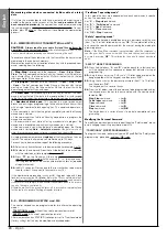
Preliminary set-up work
Dig the routes for the ducting used for electrical cables, or alternatively
external ducting can be laid, after which the pipelines can be embedded
in concrete and other preparation work for the installation can be com-
pleted to finalise the site ready for subsequent installation operations.
In particular, for digging the pit for anchoring the gearmotor to the
ground, proceed as follows:
01.
Dig the foundation pit in the gearmotor fixture point: refer to STEP
3.2
.
Note
– The dimensions of the pit must be the same or greater than
those of the foundation plate.
02.
Lay the ducting used for electrical cables as shown in the figure
below.
CAUTION!
– In general, position the ends of the ducting used for
electrical cables in the vicinity of the points envisaged for fixture of
the various components.
Note:
The ducting serves to protect electrical cables and prevent acci-
dental damage in the event of impact.
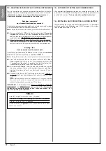
4.2
– PREPARING THE ELECTRICAL CABLES
When preparing the electrical cables required for your system, please
refer to
fig. 7
and “
Table 1 – Technical characteristics of the electric
cables
”. In addition to this, you should always remember the following:
– In the “star” configuration, NONE of the individual cables linking up
any of the devices to the Control Unit may exceed 20 m in length.
– In the “chain” configuration”, the sum of the lengths of each cable
used to connect one device to the other and, last of all, to the Con-
trol Unit MUST NOT exceed 20 m.
– If connecting other devices between the Control Unit and the flash-
ing lamp, use the same cable for these devices as was used for the
flashing lamp.
– All operations to lay the electric cables and connect them to the
various devices must be carried out during installation of the com-
ponents.
7
A
B
C
C
C
C
C


