


14
– English
English
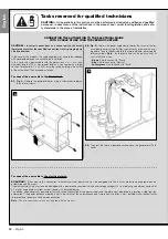
6.3
– INSTALLING AND CONNECTING
PHOTOCELLS mod. MP
A pair of photocells comprises a transmitting element (TX) and a receiving
element (RX). The photocells TX and RX are marked by a label inside the
cover.
Each photocell must be positioned on each side of transit and be facing
each other.
The system can be equipped with up to 6 pairs of photocells for safety
(enabling detection of obstacles present on the trajectory line between the
photocells) and a pair of photocells used to command an Opening
manoeuvre only (to install additional photocells, refer to section
“
Select-
ing operating modes of photocell pairs
”
).
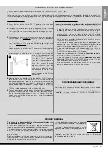
To install and connect a pair of photocells proceed as follows:
01.
Fig. 25:
Remove the screw cover cap by pushing down one side as shown in
the figure.
02.
Fig. 26:
Using a screwdriver, open and detach the base of the photocell.
03.
Fig. 27:
a)
Drill a hole on the pre-cut section on the base for routing the con-
nection cables.
b)
Fix the photocell base to the wall with the relative screws, routing
the cables through the prepared hole.
04.
Fig. 28:
a)
Connect the wires of the two cables and secure on the terminal
board.
b)
Insert the terminal board in the male connector at the rear of the
photocell.
IMPORTANT!
– Before closing the photocell, the photocell operating
mode must be selected by means of the relative jumper
(refer to sec-
tion “Selecting operating modes of photocell pairs”)
.
05.
Fig. 29:
Refit the cover, ensuring that the serrated section engages with that
of the photocell base.
06.
Fig. 30:
Fix the photocell cover to the base by means of the screw supplied.
Lastly refit the screw cover cap as shown in the figure.
25
26
27
29
30
28


