


English –
7
English
CAUTION!
- If forced to install the gearmotor on the left-hand side of
the gate, refer to the instructions in STEP 6.1.
4.1
.4 –
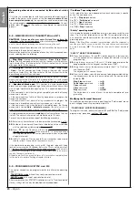
Establishing the device connection layout
The product envisages a “Bus” type connection between all system
devices, using a single cable with two electrical wires. In this type of con-
nection, data communication between devices is via cable, using the spe-
cific protocol named
“
Bus-Moovo
”.
CAUTION!
– on the Bus system, only devices compatible with this proto-
col may be installed in the system.
On a “Bus” network, devices can be connected using various connection
configurations, and in each one, each device becomes a node of this net-
work. The possible connection layouts are the following:
–
“
star
”
: In this configuration, each device is autonomous as it is connect-
ed directly to the two Bus terminals on the control unit.
–
“
chain
”
: In this configuration one device is connected to another and
the latter to another and so on, like links of a chain. Therefore only the first
device in the chain is connected to the two Bus terminals on the control
unit.
–
“
mixed
”
: this configuration is a combination of the two configurations
described above.
To select the most suitable connection configuration for the connection of
all system devices, refer to the example shown in
fig. 7
/
fig. 17
. In gener-
al, it is recommended to connect the flashing light as the first device con-
nected to the control unit.
STEP 4
4.1
– PRELIMINARY SET-UP WORK
4.1
.1 –
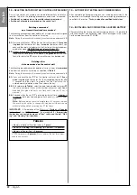
Typical reference system
Fig. 5,
shows an example of an automation system set up with
Moovo
components. These parts are positioned according to a typical standard
layout. The following components are used:
a
- Electromechanical gearmotor
b
- Rack
c
- Pair of photocells (wall-mounted)
d
- Flashing light
e
- Control keypad (wall-mounted)
f
- Pair of photocells (on posts)
4.1
.2 –
Establishing positions of components
With reference to
fig. 5
, locate the approximate position for installation of
each component envisaged in the system. In particular, to establish the
position of the flashing light, refer also to
fig. 20
.
Warning
– The “fixed” control devices must be visible from the gate but
positioned far from moving parts.
4.1
.3 –
Establishing the positions of the gearmotor
The gearmotor is factory set to be installed on the right-hand side of the
gate.
5
c
c
d
e
f
f
b
a
6


