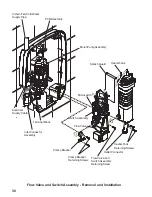
33
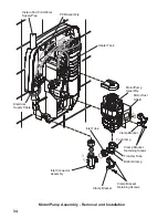
5. Motor/Pump Assembly - Removal and Installation
WARNING!
Isolate the electrical and water supplies before removing the cover. Mains
electricity connections are exposed when the cover is removed.
5.1.
Unscrew the four cover retaining screws sufficient to remove the cover and
service tunnel.
Note!
The cover retaining screws are captive and need not be removed.
5.2.
Remove the clamp bracket retaining screws from both clamp brackets. Remove
the clamp brackets.
5.3.
Remove the motor dust shield
5.4.
Ease the motor/pump assembly away from the inlet connector assembly and the
flow valve and switch assembly.
5.5.
Carefully pull the motor/pump assembly away from the case and the mounting
block.
5.6.
Make a note of the positions of the wiring on top of the motor/pump assembly.
5.7.
Remove the blue wire and the orange wire from the top of the motor/pump
assembly and remove the motor/pump.
5.8.
Install the transfer/inlet tube to the motor/pump assembly as follows:
-
Fit the transfer tube to the motor/pump assembly making sure that
the location pip on the motor/pump assembly aligns with the slot in
the transfer tube.
-
Tighten the top clamp.
-
Fit the motor/pump assembly in position and swivel the inlet tube so
that in locates correctly in the inlet connector assembly.
-
Tighten the bottom clamp.
5.9.
Refit the components in reverse order. Make sure that the electrical wires are
installed in the correct positions and that the motor dust shield is replaced.


