background image

7

6

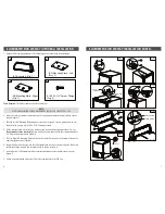
Tools Required: 

Flat head screwdriver, Philips screwdriver

NOTE:

IF THE ISD MOUNTING PLATES ARE FACTORY INSTALLED, SKIP STEPS 2 TO 5.

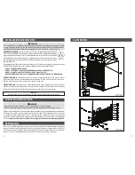
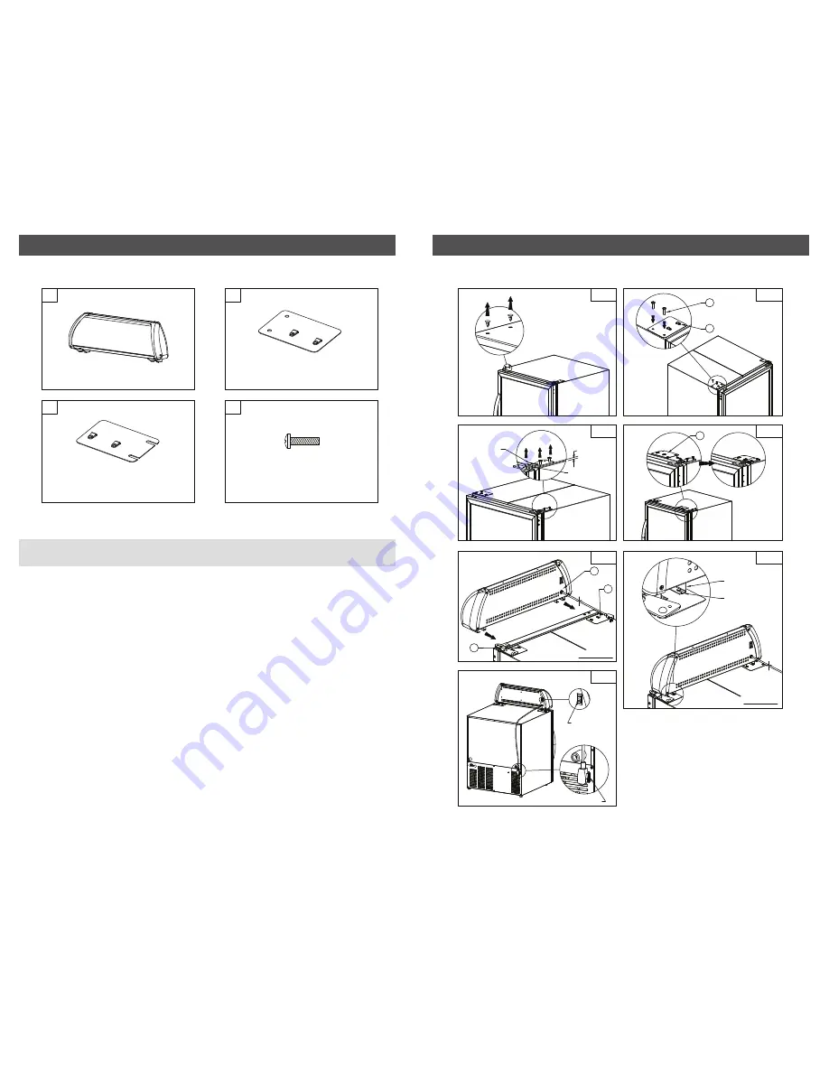
2. With a flat head screwdriver, remove the two (2) screw caps located on the top left hand side of 

the unit (figure 1).

3. Take the Left ISD Mounting Plate and place it as shown in figure 2. Line up plate holes with unit 

top and fasten using two (2) #10-32 X 3/4" Screws provided. 

4. On the top right hand side of the unit, loosen screws from the door top bracket about 1/4" out.

Do not remove screws completely

. Using a flat head screw driver lift the door top bracket about 

1/8" from the door top surface (figure 3).

5. Take the Right ISD Mounting Plate and line up slots with the screws. Push the plate all the way to 

right and tighten screws (figure 4).

6. Facing the front of the freezer, take the ISD assembly and insert it as shown in figure 5. Make sure 

each bracket leg is inserted into each plate hook as shown in figure 6.  

7. Insert plug from ISD assembly into the receptacle located on the rear bottom side of the unit

(figure 7).

8. Switch on power located at the rear of the ISD assembly to turn the LED's on. 

1.  Unpack ISD Assembly components. The following items are contained in the package: 

ISD Assembly (Qty: 1)

A

D

ISD Mounting Plate - Left

(Qty: 1)

B

C

ISD Mounting Plate - Right

(Qty: 1)

#10-32 X 3/4" Screw, Philips

(Qty: 2)

FIG. 1

FIG. 2

B

FIG. 5

FIG. 6

REAR OF UNIT

REAR OF UNIT

A

B

C

BRACKET LEG

PLATE HOOK

D

FIG. 7

SWITCH

RECEPTACLE

FIG. 3

1/8"

DOOR TOP

BRACKET

LIFT BRACKET
HERE

FIG. 4

C

ILLUMINATED SIGN DISPLAY (OPTIONAL) INSTALLATION     

ILLUMINATED SIGN DISPLAY INSTALLATION CONT’D.     

Summary of Contents for 02-CSGF

Page 1: ...ntario Canada L7G 4R9 Tel 800 800 5706 or 905 702 1441 Fax 905 702 1442 Email info minusforty com Web www minusforty com To better help you obtain assistance or service should you ever need it write d...

Page 2: ...ser Cleaning Interior LED Strip Replacement ISD LED Strip Replacement Illuminated Sign Display Installation Troubleshooting Guide Parts List Illustration Wiring Diagram Repair Service Log 1 2 2 2 3 3...

Page 3: ...Corp s factory or repair facilities if the re pairs in the judgement of Minus Forty Technologies Corp have affected the reli ability or wear of the product and nor does the guarantee apply to any pro...

Page 4: ...th fire or electrical shock DO NOT USE AN EXTENSION CORD DO NOT CUT REMOVE OR BYPASSTHE GROUNDING PRONG FROMTHE PLUG DO NOT PLUG INTO AN OUTLET CONTROLLED BY A WALL SWITCH ENSURE POWER CORD IS NOT CUT...

Page 5: ...24 Compressor 25 Overload GENERAL The freezer should be cleaned at regular intervals to meet a good standard of hygiene and to keep the freezer attractive as an effective point of purchase display IN...

Page 6: ...ks Remember the black wire must be connected to the black wire and red wire must be connected to the red wire 7 Reinstall compressor cover and reconnect power supply 9 REAR OF UNIT FRONT OF UNIT FIG 1...

Page 7: ...cian only Problem Possible Cause Action Freezer not running Fuse blown circuit breaker tripped Power cord unplugged Receptacle not working Improper voltage supplied to cabinet over load circuit Replac...

Page 8: ...h the screws Push the plate all the way to right and tighten screws figure 4 6 Facing the front of the freezer take the ISD assembly and insert it as shown in figure 5 Make sure each bracket leg is in...

Reviews: