background image

Control Panel

1-6

Introduction

Chapter 1

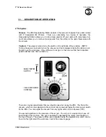
When the Ready LED is on

LED Display

Description

Response Required

Initializing

Power on, initializ-
ing.

Warming Up

Printer is warming 
up.

Ready

Printer is ready and 
able to print.

Summary of Contents for PageWorks 18L

Page 1: ...User s Manual PageWorks18L...

Page 2: ...the ENERGY STAR Guidelines for energy efficiency What is an ENERGY STAR Printer ENERGY STAR printers have a feature that allows them to automatically go to sleep after a period of inactivity This auto...

Page 3: ...int head unit The print head unit is NOT A FIELD SERVICE ITEM Therefore the print head unit should not be opened under any circum stance Laser Safety This printer is certified as a Class 1 Laser produ...

Page 4: ...ontrols adjustments or performance of procedures other than those specified in this manual may result in hazardous radia tion exposure This is a semiconductor laser The maximum power of the laser diod...

Page 5: ...user is encouraged to try to correct the interface by one or more of the follow ing measures Reorient or relocate the receiving antenna Increase the separation between the equipment and the receiver...

Page 6: ...CC regulations and any changes or modifications must be registered with the FCC and are subject to FCC control Any changes made by the purchaser or user without first contacting the manufacturer will...

Page 7: ...is released This amount is not large enough to harm anyone adversely However be sure the room where the machine is being used has adequate ventila tion especially if you are printing a high volume of...

Page 8: ...eval system or translated into other languages without the express written prior consent of Minolta Co Ltd The contents of this manual are subject to change without notice Trademark Acknowledgments PC...

Page 9: ...uestions and handles all e mail requests for technical assistance at http www minoltaprinters com Please be prepared to provide the following information when contact ing Minolta Technical Support Mod...

Page 10: ...1 5 When the Ready LED is on 1 6 When the Error LED is on 1 9 Chapter 2 Setting up Installation Precautions 2 1 Selecting a Location for the Printer 2 1 Power Source 2 2 Grounding 2 2 Space Requiremen...

Page 11: ...onal SIMM 2 14 Duplex Unit 2 19 Installing the Duplex Unit 2 19 Second Third Paper Cassette Unit 2 22 Installing the Optional Second Third Paper Cassette Unit 2 22 Network Interface Card NIC 2 26 Inst...

Page 12: ...ing the Printer Driver Under Windows 95 98 4 3 To Install the Printer Driver Using the Installer Auto Run 4 3 To Uninstall the Printer Driver 4 13 Installing the Printer Driver Under Windows NT 4 0 4...

Page 13: ...NT4 0 4 48 Common Buttons 4 49 Paper 4 50 Page Layout 4 52 Image 4 57 Device Option 4 59 About 4 59 Using the Printer Status Display 4 60 Opening the Printer Status Display 4 60 To Open the Printer S...

Page 14: ...inter 5 6 Cleaning the Outside of the Printer 5 6 Cleaning the Paper Transport Roller 5 7 Chapter 6 Troubleshooting Technical Support 6 1 Clearing a Paper Misfeed 6 2 Inside the Printer 6 2 Paper Outp...

Page 15: ...6 13 Toner smudges 6 13 No output 6 14 Are you using the correct type of printer cable 6 14 Are your computer s communications port settings correct 6 14 Messages 6 15 When the Ready LED is on 6 16 W...

Page 16: ...xiv Contents SIMM Option 7 8 Appendix A Glossary Appendix B Quick Reference Appendix C Index...

Page 17: ...Chapter Introduction 1 Introduction Chapter 1...

Page 18: ...Introduction Chapter 1...

Page 19: ...he Minolta PageWorks 18L the perfect printer for any size office Fast 18 page per minute print speed Powerful Windows printing technology for fast output Real 1200 600 dpi resolution Optional 10 100Ba...

Page 20: ...00 sheet multipurpose tray cassette unit second cassette option Face down tray Control panel Manual feed tray Paper size guide Tray cover Cassette cover option Paper size guide Power Top cover release...

Page 21: ...ories 1 3 Introduction Chapter 1 Power cord socket Image transfer roller Network Interface Card NIC option Imaging cartridge Top cover Fusing unit Parallel interface connector Ethernet interface conne...

Page 22: ...ON A Fatal Error has occurred BLINKING A recoverable error has occurred OFF Normal Toner Empty LED ON The imaging cartridge is empty BLINKING The imaging cartridge is almost empty OFF Normal Paper Emp...

Page 23: ...turn on off or blink in combination to let you know the current status of the printer You can find out details of the printer s status by checking the information that appears on your computer screen...

Page 24: ...anel 1 6 Introduction Chapter 1 When the Ready LED is on LED Display Description Response Required Initializing Power on initializ ing Warming Up Printer is warming up Ready Printer is ready and able...

Page 25: ...the trays is empty Press the Action key to see which tray is out of paper For details see Chap ter 6 Troubleshoot ing p 6 18 Size Mismatch The wrong size of paper has been detected in Tray 1 Tray 2 o...

Page 26: ...tridge is low on toner but printing is still possible Ready a new imag ing cartridge For details see Chap ter 5 Maintenance p 5 1 No Cassette No Tray No Cassette The casstte for Tray 2 or Tray 3 is no...

Page 27: ...pressing the Action key and change the paper size setting in the driver pp 3 3 6 20 Paper Misfeed A paper misfeed occurred near the Multipurpose tray Tray 2 Tray 3 Man ual feeding tray Lower duplex un...

Page 28: ...MEMO Introduction Chapter 1...

Page 29: ...Chapter Setting up 2 Setting up Chapter 2...

Page 30: ...Setting up Chapter 2...

Page 31: ...nia or other organic gases being generated in the area The power outlet you plan to connect to should be nearby and unobstructed Make sure that the printer is not exposed to direct sunlight Avoid area...

Page 32: ...oltage capacity specified for this printer Be sure to plug the power cord all the way into the outlet The outlet should be located near the printer and be easily accessible so you can unplug the power...

Page 33: ...nance When equipped with an optional third cassette unit 11 3 4 300 mm or more 29 1 2 746 mm or more 34 1 4 867 mm or more 6 150 mm or more 11 3 4 300 mm or more 23 1 2 600 mm or more 40 1 2 1 028 mm...

Page 34: ...lace flammable gasses liquids or objects that generate magnetic forces near the printer When unplugging the power cord always grasp the plug and never pull on the cord A damaged cord creates the dange...

Page 35: ...ds to spill on or near the printer Fire or electrical shock can occur should water or liquid come into contact with the printer Should liquid or any piece of metal accidently get inside the printer im...

Page 36: ...reas subjected to high humidity Areas subjected to large amounts of dust Keep paper that has been removed from its wrapper but not yet loaded onto the printer tray in a sealed plastic bag and store it...

Page 37: ...bend the face down tray inwards and insert one of its tabs into its holder on the upper portion of the printer Continue to bend the face down tray so that it curves enough for the second tab to fit i...

Page 38: ...ting up Chapter 2 Installing Tray 1 1 Using the left and right slots in the printer as guides gently push Tray 1 until it cannot be inserted any further as shown in the illustration 2 Attach the tray...

Page 39: ...pter 2 Connecting the Power Cord 1 Make sure that the printer s power switch is in the Off posi tion 2 Connect one end of the power cord that comes with the printer to the power cord socket Plug the o...

Page 40: ...2 10 Setting up Setting up Chapter 2 Loading Paper 1 Remove the tray cover from Tray 1 2 Open all three of the paper size guides...

Page 41: ...the tray print side up Secure the stack by adjusting the paper size guides Note 4 Replace the tray cover onto Tray 1 A maximum level mark on the paper size guide shows how high you can stack paper on...

Page 42: ...s that the printer is warming up In about 23 seconds only the READY indicator remains lit indicating that the printer is ready to print Note The printer automatically enters a power saving mode if it...

Page 43: ...are both turned off 2 Connect one end of the interface cable to the parallel port of the computer 3 Connect the other end of the cable to the parallel connector on the back of the printer Secure the...

Page 44: ...Optional SIMM Warning 1 Turn off the printer and unplug the power cord 2 Disconnect the parallel cable from the printer 3 Press the top cover release button and open the top cover Memory capacity can...

Page 45: ...screws that secure the exterior side cover to the printer 5 Clips secure the exterior side cover from the inside of the printer Gently maneuver the exterior side cover until the clips release see ill...

Page 46: ...e exterior side cover removed the internal side cover of the printer is exposed With the screwdriver loosen and remove the four screws that secure the internal side cover 7 Remove the internal side co...

Page 47: ...MM insert the SIMM into the socket on the main circuit Insert the SIMM at an angle as shown and gently swing it into the socket Apply pressure until the SIMM locks into place 9 Make sure both clips on...

Page 48: ...memory capacity If it does not repeat the above steps making sure that the SIMM is installed correctly See page 4 64 Displaying Printer Information Note To release the SIMM from the socket push out o...

Page 49: ...f the paper through the printer software For more information refer to page 3 15 Take the duplex unit out of the shipping box Remove the plastic bag and all shipping materials Turn the printer off and...

Page 50: ...ign the L shaped duplex unit to the back of the main unit of the printer so that the bottom of the L is inside of the opening at the bottom of the printer Note Make sure that the connector of the unit...

Page 51: ...r cord to the printer and then turn the printer on See Connecting the Power Cord page 2 9 See Turning On the Printer page 2 12 5 Select the Printer Information in the Printer Status Display to ver ify...

Page 52: ...e interchangeable and can increase paper holding capacity to 1 000 sheets when installed together Installing the Optional Second Third Paper Cassette Unit Take the paper cassette unit out of the shipp...

Page 53: ...r cassette unit using the coupling pins as a guide Note The printer weighs approximately 18 kg 39 7 lbs with the optional second paper cassette unit installed Two people are recommended to lift it whe...

Page 54: ...s Setting up Chapter 2 3 Insert Tray 2 or Tray 3 into the paper cassette unit Note Be sure to use both hands whenever Tray 2 or Tray 3 is being removed from or inserted into the paper cassette unit Tr...

Page 55: ...turn the printer on See Connecting the Power Cord page 2 9 See Turning On the Printer page 2 12 5 Select the Printer Information in the Printer Status Display to ver ify that Tray 2 or Tray 3 is displ...

Page 56: ...network interface card that is supported by this printer For details please see the User s Manual for the Network Interface Card Installing the Optional Network Interface Card 1 Turn the printer off...

Page 57: ...C out of its carton Note 4 Insert the NIC as shown in the diagram Make sure that you do not misplace the cover panel or screws when you remove them The screws will be used after the optional NIC is in...

Page 58: ...same screws that were used to hold the cover panel Note 6 Connect the power cord to the printer and then turn the printer on See Connecting the Power Cord page 2 9 See Turning On the Printer page 2 1...

Page 59: ...Chapter Using the Printer 3 Using the Printer Chapter 3...

Page 60: ...Using the Printer Chapter 3...

Page 61: ...d Paper weighing 60 to 90 g m2 16 to 24 lbs Trans parency Sheet Labels Letter head Enve lopes J Post Post card size 100 148 mm 4 5 3 4 Thick Paper weighing 90 to 163 g m2 24 to 43 lbs Tray 1 Tray 2 No...

Page 62: ...surfaces that are too smooth or too rough or with varying surfaces Paper having special coatings on their surfaces such as carbon paper heat sensitive paper and pressure sensitive paper Sheets of vari...

Page 63: ...to the printer Various types and sizes of paper can be fed from this tray Tray 2 Tray 3 are available as optional paper sources See the section of this User s Manual entitled Loading Paper onto Tray 2...

Page 64: ...inter Chapter 3 Loading Paper onto Tray 1 You can load up to 250 sheets of standard paper onto Tray 1 See page 3 1 for details on paper sizes and types 1 Remove the tray cover from Tray 1 2 Open all t...

Page 65: ...des so that both the left and the right sides of the paper stack are secure Note A maximum level mark on the paper size guide shows how high you can stack paper on Tray 1 Make sure that paper is stack...

Page 66: ...3 6 Loading Paper Using the Printer Chapter 3 4 Replace the tray cover onto Tray 1...

Page 67: ...oving the Tray 2 Tray 3 cassette into and from the second third paper cassette unit refer to Chapter 2 The cassette is designed to remain in the unit during the normal loading and operation of the pri...

Page 68: ...3 8 Loading Paper Using the Printer Chapter 3 2 Remove the cassette cover from Tray 2 Tray 3 3 Press down on the paper lifting plate located inside of Tray 2 Tray 3 until it locks...

Page 69: ...s unwrapped is still facing up Note A maximum level mark inside the inlet of Tray 2 Tray 3 shows how high you can stack paper Make sure that paper is stacked no higher than this mark Tray 2 Tray 3 doe...

Page 70: ...3 10 Loading Paper Using the Printer Chapter 3 5 Replace the cassette cover and insert Tray 2 Tray 3 into the second third paper cassette unit Tray 2 Tray 3...

Page 71: ...ter Chapter 3 Loading Paper onto Manual Feed Tray 1 Make sure that the tray cover is properly attached to Tray 1 2 Open the paper size guides 3 Insert the sheet of paper into the manual feed tray with...

Page 72: ...12 Loading Paper Using the Printer Chapter 3 4 Adjust the paper size guides so that both sides of the paper are secure Note Insert only one sheet of paper or one envelope at a time when feeding manual...

Page 73: ...hould be facing down and to the left 2 Make sure that the envelope is placed in the center of the tray and that it is secured by the paper size guides Note Note the following points whenever printing...

Page 74: ...ch flaps run the entire length of the envelope Envelopes that seal at one end will not feed properly Do not use envelopes that have a window Such envelopes can seri ously damage the printer Do not use...

Page 75: ...both sides of a sheet of paper Installation of the optional duplex unit is required to perform duplex printing You can choose either Long Edge Binding or Short Edge Binding when generating duplex docu...

Page 76: ...per Size A4 A5 JIS B5 Letter Legal Executive Invoice Remember the following points when generating duplex documents The size of both original documents that will be used to make one duplex document mu...

Page 77: ...Chapter Printer Driver and Status Display 4 Printer Driver and Status Display Chapter 4...

Page 78: ...Printer Driver and Status Display Chapter 4...

Page 79: ...dows 95 Windows 98 or Windows NT 4 0 Personal Computer IBM compatible PC with at least a 486DX 66MHz CPU Pentium processor recommended Disk Drive One CD ROM drive is required for installation I O Inte...

Page 80: ...be equipped with at least 16 MB Windows 95 98 or 32 MB Windows NT 4 0 of RAM Additional RAM beyond the recommended 32 MB Windows 95 98 or 64 MB Windows NT 4 0 will allow your printer to provide you wi...

Page 81: ...er driver must be installed using the CD ROM s installer To Install the Printer Driver Using the Installer Auto Run 1 Turn on your computer and start up Windows 95 or Windows 98 2 Insert the Printer D...

Page 82: ...the printer is connected directly to your computer or Network printer if the printer is connected through a network and click OK 6 Select an installation option and click OK The printer driver must be...

Page 83: ...nographic s ZScript User s Guide file name ZScript pdf from the Manual folder in the CD ROM Displaying Zenographic s ZScript User s Guide File 1 After you complete installation of the GDI Printer Driv...

Page 84: ...iate port 8 Check Set as default printer if you want to use the printer as this default printer or leave this option unchecked if you do not want it as the default 9 Click the OK button to display the...

Page 85: ...Status Display Chapter 4 11 Change the directory name if you want or leave the default direc tory name Next click Install to start actual GDI Printer Driver installation 12 Click Yes recommended to pr...

Page 86: ...s a Masquerade icon Note 14 On the Installer screen click the Quit button 15 To start installation of PostScript Driver ZScript double click the Masquerade icon in the Minolta Printer Utilities dialog...

Page 87: ...95 98 Printer Driver and Status Display Chapter 4 16 In the Non PostScript Printers area select Minolta PageWorks Pro 18L on LPT1 and then click the Install button 17 After a few moments the Minolta...

Page 88: ...iver and Status Display Chapter 4 18 Click OK to display the next dialog 19 Confirm that Minolta PageWorks Pro PSCRIPT is in the Installed ZScript Printers area of the Masquerade dialog 20 Click the E...

Page 89: ...point to Settings and then click Printers 22 Confirm that two icons named Minolta PageWorks Pro 18L and Minolta PageWorks Pro PSCRIPT are shown in the Printers dialog Note The Minolta PageWorks Pro PS...

Page 90: ...Driver and Status Display Chapter 4 Print Test Page Example An example of the test page is shown below Make sure that Minolta PageWorks Pro 18L is indicated as the printer model on the test page This...

Page 91: ...n on your computer and start up Windows 95 or Windows 98 2 To start uninstallation of PostScript Driver ZScript click Start on the taskbar point to Programs point to Minolta Printer Utili ties and the...

Page 92: ...nstalling the Printer Driver Under Windows 95 98 Printer Driver and Status Display Chapter 4 3 In the Installed ZScript Printers area click Minolta Page Works Pro PSCRIPT and then click Remove 4 Click...

Page 93: ...ar click Start point to Settings and then click Printers 6 Confirm that the Minolta PageWorks Pro PSCRIPT icon is no longer displayed in the Printers dialog 7 To start uninstallation of the GDI Printe...

Page 94: ...uninstall operation or No to abort Note 9 Click Yes to delete the directory that contains the Minolta Printer Utilities program 10 In the next dialog that appears click Yes to restart the computer Th...

Page 95: ...er Under Windows 95 98 Printer Driver and Status Display Chapter 4 11 On the taskbar click Start point to Settings and then click Printers 12 Confirm that the Minolta PageWorks Pro 18L icon is no long...

Page 96: ...e printer driver on a computer running Windows NT 4 0 It also tells you how to uninstall the printer driver when necessary To Install the Printer Driver Using the Installer Auto Run 1 Turn on your com...

Page 97: ...5 Select Local Printer 6 Click the OK button to display the next dialog The configuration of some computers may prevent the opening screen from appearing automatically If the screen does not appear do...

Page 98: ...4 20 Installing the Printer Driver Under Windows NT 4 0 Printer Driver and Status Display Chapter 4 7 Select installation options...

Page 99: ...Zenographic s ZScript User s Guide file name ZScript pdf from the Manual folder in the CD ROM Displaying Zenographic s ZScript User s Guide File 1 After you complete installation of the GDI Printer Dr...

Page 100: ...checkbox Note 9 If you plan to use the printer as a network printer type in a name for Share Name Example PWP_18L Note 10 Click OK to display the next dialog 11 Select the appropriate port If your pri...

Page 101: ...eck Set as default printer if you want to use the printer as this default printer or leave this option unchecked if you do not want it as the default 13 Click the OK button to display the next dialog...

Page 102: ...Status Display Chapter 4 15 Change the directory name if you want or leave the default direc tory name Next click Install to start actual GDI Printer Driver installation 16 Click Yes recommended to p...

Page 103: ...as a Masquerade icon Note 18 On the Installer screen click the Quit button 19 To start installation of PostScript Driver ZScript double click the Masquerade icon in the Minolta Printer Utilities dialo...

Page 104: ...NT 4 0 Printer Driver and Status Display Chapter 4 20 In the Non PostScript Printers area select Minolta PageWorks Pro 18L on LPT1 and then click the Install button 21 After a few moments the Minolta...

Page 105: ...river and Status Display Chapter 4 22 Click OK to display the next dialog 23 Confirm that Minolta PageWorks Pro PSCRIPT is in the Installed ZScript Printers area of the Masquerade dialog 24 Click the...

Page 106: ...icons named Minolta PageWorks Pro 18L and Minolta PageWorks Pro PSCRIPT are shown in the Printers dialog Note The Minolta PageWorks Pro PSCRIPT icon does not appear in the Printers dialog if you do no...

Page 107: ...Driver and Status Display Chapter 4 Print Test Page Example An example of the test page is shown below Make sure that Minolta PageWorks Pro 18L is indicated as the printer model on the test page This...

Page 108: ...1 Turn on your computer and start up Windows NT 4 0 2 To start uninstallation of PostScript Driver ZScript click Start on the taskbar point to Programs point to Minolta Printer Utili ties and then cl...

Page 109: ...nstalling the Printer Driver Under Windows NT 4 0 Printer Driver and Status Display Chapter 4 3 In the Installed Zscript Printers area click Minolta PageWorks Pro PSCRIPT and then click Remove 4 Click...

Page 110: ...ar click Start point to Settings and then click Printers 6 Confirm that the Minolta PageWorks Pro PSCRIPT icon is no longer displayed in the Printers dialog 7 To start uninstallation of the GDI Printe...

Page 111: ...uninstall operation or No to abort Note 9 Click Yes to delete the directory that contains the Minolta Printer Utilities program 10 In the next dialog that appears click Yes to restart the computer Th...

Page 112: ...er Under Windows NT 4 0 Printer Driver and Status Display Chapter 4 11 On the taskbar click Start point to Settings and then click Printers 12 Confirm that the Minolta PageWorks Pro 18L icon is no lon...

Page 113: ...StartUp directory of Windows 95 Windows 98 or Windows NT 4 0 allows the Status Display to automatically reside on your desktop Follow the instructions provided for registering the Status Display acco...

Page 114: ...Display registration under Windows 95 Actual screen images may appear differently under Windows 98 however the registration procedure is the same This procedure must be followed only after the succes...

Page 115: ...og 4 Use the Browse button to search for the Zjst402w file for this example it is assumed that the file is installed under C Windows Zjst402w exe 5 Click the Windows file and then click the Open butto...

Page 116: ...elect the StartUp folder from the Select folder to place shortcut in box and then click Next 9 Enter a name for the shortcut to the Status Display into the Select a Title for the Program dialog and cl...

Page 117: ...g the Status Display Printer Driver and Status Display Chapter 4 12 Make sure that the Minolta PageWorks Pro 18L Status Display appears on your desktop and that the Status Display icon appears on the...

Page 118: ...Status Display Under Windows NT 4 0 This procedure must be followed only after the successful installation of the printer driver 1 Click on the Start button go to the Settings menu and click on the Ta...

Page 119: ...alog 4 Use the Browse button to search for the Zjst402w file for this example it is assumed that the file is installed under C Winnt Zjst402w exe 5 Click the Winnt file and then click the Open button...

Page 120: ...elect the Startup folder from the Select folder to place shortcut in box and then click Next 9 Enter a name for the shortcut to the Status Display into the Select a Title for the Program dialog and cl...

Page 121: ...g the Status Display Printer Driver and Status Display Chapter 4 12 Make sure that the Minolta PageWorks Pro 18L Status Display appears on your desktop and that the Status Display icon appears on the...

Page 122: ...ollowing procedure to display the driver setup dialog under Windows 95 Windows 98 or Windows NT 4 0 To Display the Driver Setup Dialog Under Windows 95 98 1 Click Start point to Settings and then clic...

Page 123: ...4 45 Displaying the Driver Setup Dialog Windows 95 98 NT 4 0 Printer Driver and Status Display Chapter 4 4 On the 32 bit SuperDriver Setup tab of the Properties dialog the following dialog appears...

Page 124: ...lay Chapter 4 To Display the Driver Setup Dialog Under Windows NT 4 0 1 Click Start point to Settings and then click Printers to display the Printers dialog 2 In the Printers dialog click the Minolta...

Page 125: ...4 47 Displaying the Driver Setup Dialog Windows 95 98 NT 4 0 Printer Driver and Status Display Chapter 4 4 The following dialog appears...

Page 126: ...y of printer parameters from your computer The following sections provide an overview of the printer driver s properties The settings that are specified in the Properties dialog will become the defaul...

Page 127: ...on Buttons The following buttons appear at the bottom of each tab OK Click to exit the properties dialog saving any changes made Cancel Click to exit the properties dialog without saving any changes m...

Page 128: ...Paper Size The various sizes of paper that are supported by your printer are displayed in the drop down list Select the appropriate size Paper Envelopes Letter 8 1 2 11 inches Legal 8 1 2 14 inches In...

Page 129: ...ge Landscape Landscape documents are printed widthwise horizontally relative to the page Paper Source The Paper Source item specifies the tray from which paper is fed from the printer To change this s...

Page 130: ...on a single page Click on the drop down list to view the possible selections Off This default setting specifies one document per sheet of paper 2 up This setting will print two documents onto one shee...

Page 131: ...ontal descending vertical ascending and vertical descending Note Watermark Watermarks are placed on a document to quickly alert the reader to the nature of its content For example CONFIDENTIAL DRAFT e...

Page 132: ...shadow text behind the actual content of the document When the In Background box is not checked watermarks are superimposed over the actual content of the document Watermark pop up dialog To open the...

Page 133: ...e of the watermark s font Font The typeface and size of the watermark is specified here Angle Rotate the angle of the watermark s placement through the value specified in this box Position Adjust the...

Page 134: ...t double sided printing From the drop down list select Short Edge Binding to print documents in a calendar style format Long Edge Binding to print documents in a book style format or Off for one sided...

Page 135: ...setting is optimal for printing documents that will be sent via facsimile Enhance Contrast This setting enhances the definition between dark and light Resolution The resolution setting determines the...

Page 136: ...of Contrast Brightness and Sharpness Usually the median values toward the center of the bars will provide the best display To fine tune these settings click hold and move the sliders in order to make...

Page 137: ...tallable Options list to the Installed Options list select the option and click the Add button The Installed Options list catalogs the optional accessories that have been added to your printer To remo...

Page 138: ...cable Use the procedure below to open the Printer Status Display To Open the Printer Status Display Click Start point to Programs point to Minolta Printer Utilities and then click Minolta PageWorks Pr...

Page 139: ...of what you need to do in order to correct problems and recover from error conditions Warning Status This area displays text messages that warn you of such conditions as low toner Printer Status figu...

Page 140: ...ror conditions that do not cause popup error messages to appear To move an error condition from the Inactivate Popup list to the Activate Popup list click on the error condition to highlight it and th...

Page 141: ...witch between the expanded and reduced views of the Printer Status Display On the Display menu click Reduce to reduce the size of the display or Expand to expand it The expanded view is the normal siz...

Page 142: ...here to indicate when a second cassette unit has been installed onto the printer Tray 3 Tray 3 Installed will be displayed here to indicate when a third cassette unit has been installed onto the prin...

Page 143: ...Chapter Maintenance 5 Maintenance Chapter 5...

Page 144: ...Maintenance Chapter 5...

Page 145: ...the toner remaining in the cartridge Prepare a new imaging cartridge as a replacement When the imaging cartridge runs out of toner Imaging Cartridge Empty message is displayed in the Status Display It...

Page 146: ...on 1 Turn the printer off and then disconnect the power cord and interface cable from the printer 2 Close the face down tray and press the top cover release button to open the top cover The fusing uni...

Page 147: ...ove the old imaging cartridge Note Be sure to close the face down tray before opening the top cover to prevent injuries Do not touch the shutter of the imaging cartridge to avoid causing damage to the...

Page 148: ...tridge out of the box Holding it with both hands shake it 4 or 5 times in the direction of the arrows to distribute the toner evenly 5 Install the imaging cartridge securely into the printer by slidin...

Page 149: ...5 5 Replacing the Imaging Cartridge Maintenance Chapter 5 6 Close the top cover and press it down gently but firmly until it locks into place...

Page 150: ...of the Printer Wipe the outside of the printer with a soft cloth moistened with a neutral household detergent Use a soft cloth to clean the printer Never use abrasives or corrosive detergents The fus...

Page 151: ...the Paper Transport Roller 1 Turn off the printer and unplug the power cord 2 Close the face down tray and press the top cover release button to open the top cover Note Be sure to close the face down...

Page 152: ...r 5 3 Remove the imaging cartridge Note 4 Pull back on the cover that protects the paper transport roller located at the bottom of the printer chamber Immediately wrap the imaging cartridge with a clo...

Page 153: ...5 9 Cleaning the Printer Maintenance Chapter 5 5 Use a soft cloth to wipe the paper transport roller 6 Reinstall the imaging cartridge as shown on page 5 4 and 5 5...

Page 154: ...5 10 Cleaning the Printer Maintenance Chapter 5 7 Close the top cover and press it down gently but firmly until it locks into place...

Page 155: ...Chapter Troubleshooting 6 Troubleshooting Chapter 6...

Page 156: ...Troubleshooting Chapter 6...

Page 157: ...y Asked Questions and handles all e mail requests for technical assistance at http www minoltaprinters com Please be prepared to provide the following information when contacting Minolta Technical Sup...

Page 158: ...a misfed paper from inside the printer Caution 1 Close the face down tray and press the top cover release button to open the top cover Note The fusing unit inside the printer can become very hot duri...

Page 159: ...6 3 Clearing a Paper Misfeed Troubleshooting Chapter 6 2 Remove the imaging cartridge Note Immediately wrap the imaging cartridge with a cloth to protect it from overexposure to light...

Page 160: ...6 4 Clearing a Paper Misfeed Troubleshooting Chapter 6 3 Pull the end of the paper that is visible straight out of the printer Caution Do not touch the image transfer roller...

Page 161: ...5 Clearing a Paper Misfeed Troubleshooting Chapter 6 4 Reinstall the imaging cartridge as shown on page 5 4 and 5 5 5 Close the top cover and press it down gently but firmly until it locks into place...

Page 162: ...6 6 Clearing a Paper Misfeed Troubleshooting Chapter 6 Paper Output Misfeed Pull the misfed paper straight out of the printer...

Page 163: ...d Troubleshooting Chapter 6 Paper Input Misfeed from Tray 1 Remove the tray cover and pull the misfed paper straight out of the printer Paper Input Misfeed from Manual Feed Tray Pull the misfed paper...

Page 164: ...Cassette Unit Remove the cassette cover and pull out Tray 2 Tray 3 from the second third paper cassette unit Press down on the stack of paper until the paper lifting plate locks Remove the stack of pa...

Page 165: ...leshooting Chapter 6 Paper Misfeed in the Duplex Unit Upper Misfeed Open the duplex upper cover and pull out the misfed paper Lower Misfeed Open the duplex lower cover and remove the misfed paper Dupl...

Page 166: ...he imaging cartridge and rock it left and right a few times to distribute remaining toner If the problem persists replace the imaging cartridge page 5 2 The imaging cartridge may be defective Remove t...

Page 167: ...distribute remaining toner If the problem persists replace the imaging cartridge page 5 2 The imaging cartridge may be defective Remove the imaging cartridge and check it for damage Replace the imagin...

Page 168: ...ing car tridge Remove the imaging cartridge and rock it left and right a few times to distribute remaining toner The imaging cartridge may be defective Remove the imaging cartridge and check it for da...

Page 169: ...r smudges The toner may be unevenly dis tributed inside the imaging car tridge Remove the imaging cartridge and rock it left and right a few times to distribute remaining toner The imaging cartridge m...

Page 170: ...print and close all the applications currently open on your computer Next reset your computer to send a break signal to the printer Now check your printer cable against the specifications in Chapter 7...

Page 171: ...or blinking Error LED See the explanation for Error on the LED chart p 6 20 The LED display will change as you press the Action key The appearance of this icon throughout this manual indi cates when y...

Page 172: ...ges Troubleshooting Chapter 6 When the Ready LED is on 1 4 LED Display Description Response Required Initializing Power on initializ ing Warming Up Printer is warming up Ready Printer is ready and abl...

Page 173: ...entered the Power Save Mode Toner Low The imaging car tridge is low on toner but printing is still possible Prepare to replace the imaging car tridge with a new one p 5 1 Wait Action Press the Action...

Page 174: ...Tray 2 Paper Empty The paper supply of Tray 2 is empty Add paper p 3 7 Tray 3 Paper Empty The paper supply of Tray 3 is empty Size Mismatch The wrong size of paper has been detected in Tray 1 Tray 2 o...

Page 175: ...iver and resend the print job p 4 51 Tray 3 No Cassette No Tray 3 The cassette for Tray 3 is not in place Check the trays to make sure that all cassettes are securely in place p 2 22 A print job was s...

Page 176: ...hen on again and resend the print job Lower the resolu tion setting or increase the amount of memory installed in the printer and resend the print job Cover Open The cover is open Paper Size Error The...

Page 177: ...isfeed 1 A paper misfeed occurred near the multipurpose tray Remove the misfed sheet of paper For details see Clear ing a Paper Mis feed p 6 2 Paper Misfeed 2 A paper misfeed occurred near Tray 2 Pape...

Page 178: ...A paper misfeed occurred near the lower duplex unit Remove the misfed sheet of paper For details see Clear ing a Paper Mis feed p 6 2 Paper Misfeed 6 A paper misfeed occurred near the imaging cartrid...

Page 179: ...Unit The cover of the duplex unit is open Wrong Media Duplex Unit The wrong media has been loaded into the duplex unit Place the specified type of paper into the correct tray p 3 16 Wrong Size Duplex...

Page 180: ...urn the printer off then on again and resend the print job Lower the resolution setting and resend the print job I O Error Parallel A controller error occurred at the paral lel port Turn the printer o...

Page 181: ...on 6 8 LED Display Description Response Required Fatal Error HSYNC Abnormal An engine error has occurred Turn the printer off then on again If the problem persists contact customer support or your dea...

Page 182: ...iption Response Required Fatal Error Fuser Low Temperature An engine error has occurred Turn the printer off then on again If the problem persists contact customer support or your dealer Fatal Error F...

Page 183: ...ponse Required Fatal Error Fuser Warm Up An error occurred at the fusing unit Turn the printer off then on again If the problem persists contact customer support or your dealer Fatal Error Fuser Fan A...

Page 184: ...MEMO Troubleshooting Chapter 6...

Page 185: ...Chapter Specifications 7 Specifications Chapter 7...

Page 186: ...Specifications Chapter 7...

Page 187: ...izes A4 A5 JIS B5 DL Envelope C5 Envelope Letter Legal Executive Invoice Com 10 Envelope Monarch Envelope J Post Media Plain paper 60 to 90 g m2 16 to 24 lbs recycled paper 60 to 90 g m2 16 to 24 lbs...

Page 188: ...tridge that comes with the printer is capable of producing approximately 5 000 A4 size prints Power supply 120 127 V 50 60 Hz Acoustic noise 67 dB A max operating 33 dB A max power saving mode Externa...

Page 189: ...7 3 PageWorks 18L Printer Specifications Chapter 7 Options Second paper cassette unit Third paper cassette unit Duplex unit DRAM SIMM NIC Network Interface Card options available from local dealer...

Page 190: ...16 to 24 lbs recycled paper 60 to 90 g m2 16 to 24 lbs Paper cassettes Letter Option Legal Executive A4 JIS B5 Tray capacity Up to 500 sheets plain and recycled paper Operating temperature 10 to 35 C...

Page 191: ...6 to 24 lbs recycled paper 60 to 90 g m2 16 to 24 lbs Paper cassettes Letter Option Legal Executive A4 JIS B5 Tray capacity Up to 500 sheets plain and recycled paper Operating temperature 10 to 35 C O...

Page 192: ...Ordinary plain paper 64 to 90 g m2 17 to 24 lbs recycled paper 64 to 90 g m2 17 to 24 lbs Paper size A4 A5 JIS B5 Letter Legal Executive Invoice Operating temperature 10 to 35 C Operating humidity 15...

Page 193: ...ed below Length Less than 10 feet 3 meters Connectors Printer Parallel 36 pin connector PC EIA 25 pin connector Cable type Shielded Each signal and ground pair should be twisted Pin assignments IEEE 1...

Page 194: ...MM Option You can expand printer memory by adding a single in line memory module SIMM SIMMs are available from Minolta Technical Support Capacity 8 16 MB Parity Non parity Type EDO Extended Data Out A...

Page 195: ...Appendix Glossary A Glossary Appendix A...

Page 196: ...Glossary Appendix A...

Page 197: ...se button quickly Often used to select an object SEE double click control panel A bank of indicators that show the current status of the printer Panel buttons that are located on the control panel mak...

Page 198: ...output from the printer The tray can hold up to 250 sheets of paper 500 sheet second cassette option SEE Tray 2 500 sheet third cassette option SEE Tray 3 fusing unit A part of the printer that fixes...

Page 199: ...of paper Network Interface Card NIC option Facilitates the network connection of the printer off line A state in which the printer cannot receive data or perform any other operation on line A state in...

Page 200: ...a printer PostScript Developed by Adobe Systems PostScript is one of the most well known page description languages PostScript fonts Precise high quality fonts that are engineered to be printed using...

Page 201: ...that is contained in a cartridge top cover A cover attached to the printer that swings open by pressing a release button Opening the cover provides easy access to the interior of the printer to perfo...

Page 202: ...stalled into the third paper cassette unit SEE third paper cassette unit Each cassette can hold up 500 sheets of one of the following paper sizes A4 JIS B5 Legal Letter and Executive typeface Refers t...

Page 203: ...Appendix Quick Reference B Quick Reference Appendix B...

Page 204: ...Quick Reference Appendix B...

Page 205: ...er Use the LED display in combination with the Troubleshooting chapter of this manual to maintain the high level of performance that your printer was engineered to provide Indicator lights Action key...

Page 206: ...n the Ready LED is on 1 2 Initializing p 6 16 Warming Up p 6 16 Ready p 6 16 Power Save p 6 17 Toner Low pp 5 1 6 17 Wait Action p 6 17 Tray 1 Paper Empty pp 2 10 3 4 6 18 Tray 2 Paper Empty pp 3 7 6...

Page 207: ...ick Reference Appendix B When the Ready LED is on 2 2 Size Mismatch pp 3 1 4 50 6 18 Tray 2 No Cassette No Tray 2 pp 2 22 4 51 6 19 Tray 3 No Cassette No Tray3 pp 2 22 4 51 6 19 Duplex Unit Not Avail...

Page 208: ...LED is on 1 2 Buffer Overflow p 6 20 Cover Open pp 1 3 6 20 Paper Size Error pp 3 1 4 50 6 20 Paper Misfeed 1 pp 6 7 6 21 Paper Misfeed 2 pp 6 8 6 21 Paper Misfeed 3 pp 6 8 6 21 Paper Misfeed 4 pp 6 7...

Page 209: ...isfeed 7 pp 6 2 6 22 Paper Misfeed 8 pp 6 9 6 22 CoverOpen DeplexUnit pp 2 19 6 9 6 23 Wrong Media Duplex Unit pp 3 16 6 23 Wrong Size Duplex Unit pp 3 16 6 23 Video Under Run p 6 24 I O Error Paralle...

Page 210: ...en the Error LED is on Fatal Error 1 1 HSYNC Abnormal p 6 25 Polygonal Mirror Motor p 6 25 Main Motor p 6 25 Fuser Low Temperature p 6 26 Fuser Overheat p 6 26 SRAM DRAM ROM Engine I F CPU p 6 26 Fuse...

Page 211: ...Appendix Index C Index Appendix C...

Page 212: ...Index Appendix C...

Page 213: ...splaying the Driver Setup Dialog Windows 95 98 NT 4 0 4 44 Duplex Printing 3 15 Duplex Unit 2 19 7 6 E Energy Star Information inside of front cover Ethernet interface connector 10 100BaseT 1 3 F Face...

Page 214: ...Replacing the Imaging Cartridge 5 1 S Safety information i Second Third Paper Cassette Unit 1 2 2 22 7 4 7 5 Selecting a Location for the Printer 2 1 Setting up 2 7 SIMM 2 14 7 8 Space Requirements 2...

Page 215: ...2 Tray 3 500 sheet third cassette 1 2 Tray cover 1 2 Turning On the Printer 2 12 U Using the Printer Driver Under Windows 95 98 NT 4 0 4 48 Using the Printer Status Display 4 60 4 61 W When the Ready...

Page 216: ...MEMO...

Page 217: ...MEMO...

Page 218: ...MEMO...

Page 219: ...chome Azuchi machi Chuo ku Osaka 541 8556 Japan 4110 7709 01 1999 3 Copyright 1999 MINOLTA CO LTD Printed in Japan The information contained in this manual is subject to change without notice to inco...

Reviews: