background image

Minn Kota Consumer & Technical Service 
Johnson Outdoors Marine Electronics, Inc. 
PO Box 8129 
Mankato, MN  56001

121 Power Drive 
Mankato, MN 56001 
Phone (800) 227-6433 
Fax (800) 527-4464

minnkotamotors.com

©2020 Johnson Outdoors Marine Electronics, Inc.  

All rights reserved.  

Part #2354910

Rev B 

06/20

ECN 40715

For warranty information, please visit 
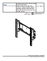
minnkotamotors.com.

NOTICE: 

The Mounting Holes on the Jack Plate 

are slotted so that the Raptor can be adjusted along 
the slots for the final installation.  

3

3d

3d

d.  With the Flange Nuts in place, pull the Red Retainer 

out to release the hardware. There are handles on 
each side of the Red Retainer that can be used to 
grasp each half. When pulling the Red Retainer, 
grasp each side and pull so that the Red Retainer 
breaks at the center and releases the hardware.

3e

Red  

Red  

Retainer

Retainer

Red  

Red  

Retainer

Retainer

Break Point

Break Point

Flange Nuts

Flange Nuts

Slotted 

Slotted 

Holes

Holes

Starboard 

Starboard 

Bracket

Bracket

Break 

Break 

Point

Point

Handle

Handle

Handle

Handle

Handle

Handle

e.  With the Red Retainer removed, there is slack in 

the mounting hardware between the Starboard 
Jack Plate Bracket and Built-in Mounting Bracket. 
This allows the Built-in Mounting Bracket and 
Raptor to be rotated for final Raptor placement 
along the Slotted Holes in the Starboard Bracket. 
Check the angle of the bracket along the Slotted 
Holes and confirm that the Raptor is set at the 
desired angle. Once set, hold the hardware inside 
the Jack Plate Bracket with a 9/16” Open End 
Wrench. Tighten the Flange Nuts with a 9/16” Box 
End or Socket Wrench. Do not over-tighten. Tighten 
to 20 ft-lbs.

Summary of Contents for 1810360

Page 1: ...ased on if a 4 1810360 or 1810365 white or 6 1810362 or 1810367 white Starboard rise was selected This kit is mounted directly to the Starboard side of a Jack Plate It may also be mounted directly to a Raptor Universal Sandwich Adapter 1810372 or 1810377 white The Raptor 3 Setback Bracket 1810370 or 1810375 white may be added to these Jack Plate brackets for additional mounting options 4 2 16 22 2...

Page 2: ...deploy and retract without hitting trim tabs poling platforms ladders the engine or other obstructions You should also consider your fishing methods when selecting the mounting location Make sure that no interference exists between the Raptor and your engine during normal operation With the location selected trim the engine all the way up and all the way down and steer the engine fully to the left...

Page 3: ...rd Starboard Bracket Bracket c With the Starboard Bracket aligned take two 3 Stainless Steel Hex Head Cap Screws Item 18 and two Heavy Duty Stainless Steel Washers Item 14 Place one Heavy Duty Washer on each of the Hex Head Cap Screws Apply anti seize on the threads of the Hex Head Cap Screws Item 22 d Insert the Hex Head Cap Screws with the Heavy Duty Washers in place through the Mounting Holes i...

Page 4: ...ex Head Cap Screws Item 22 d Insert the Hex Head Cap Screws with the Heavy Duty Washers in place through the Mounting Holes in the Starboard Bracket and into the Mounting Holes on the Starboard Side of the Jack Plate e Take two Heavy Duty Stainless Steel Washers Item 14 and place one on the end of each Hex Head Cap Screw on the inside of the Jack Plate Secure the hardware with two Stainless Steel ...

Page 5: ...ICE To prevent seizing of the stainless steel hardware do not use high speed installation tools Applying an anti seize may help prevent seizing NOTICE The hardware on the inside of the Jack Plate is secured into the Inner Threaded Plate Two of the Heavy Duty Stainless Steel Washers Item 14 and two of the Nylock Nuts Item 16 will not be used 2 x 1 18 X 2 4 x 1 14 x 2 2e 2c Outboard Outboard CAUTION...

Page 6: ...the Starboard Bracket aligned take two 3 Stainless Steel Hex Head Cap Screws Item 18 and two Heavy Duty Stainless Steel Washers Item 14 Place one Heavy Duty Washer on each of the Hex Head Cap Screws Apply anti seize on the threads of the Hex Head Cap Screws Item 22 d Insert the Hex Head Cap Screws with the Heavy Duty Washers in place through the Mounting Holes in the Starboard Bracket and into the...

Page 7: ...y Stainless Steel Washers Item 14 Place one Heavy Duty Washer on each of the Hex Head Cap Screws Apply anti seize on the threads of the Hex Head Cap Screws Item 22 d Insert the Hex Head Cap Screws with the Heavy Duty Washers in place through the Mounting Holes in the Starboard Bracket and Spacer Block and into the Holes on the Starboard Side of the Jack Plate e Take two Heavy Duty Stainless Steel ...

Page 8: ...ate Bracket aligns with the Mounting Holes in the Built in Mounting Bracket Apply Anti sieze Item 22 to the threads of the hardware held in place by the Red Retainer Then install the Built in Mounting Bracket to the hardware 2b 2c Starboard Starboard Bracket Bracket Mounting Mounting Holes Holes Jack Plate Jack Plate Bracket Bracket Flange Flange Nuts Nuts Built in Built in Mounting Bracket Mounti...

Page 9: ... side and pull so that the Red Retainer breaks at the center and releases the hardware 3e Red Red Retainer Retainer Red Red Retainer Retainer Break Point Break Point Flange Nuts Flange Nuts Slotted Slotted Holes Holes Starboard Starboard Bracket Bracket Break Break Point Point Handle Handle Handle Handle Handle Handle e With the Red Retainer removed there is slack in the mounting hardware between ...

Page 10: ...0 2 cm 1810360 ou 1810365 blanc ou de 6 po 15 2 cm 1810362 ou 1810367 blanc a été sélectionné L assemblage est monté directement côté tribord du timon Il peut aussi être monté directement à un adaptateur en sandwich universel Raptor 1810372 ou 1810377 blanc Le support de décalage de 3 po 7 6 cm 1810370 ou 1810375 blanc peut être ajouté aux supports de timon pour plus d options de montage 4 2 16 22...

Page 11: ...e la sélection de l emplacement de montage S assurer qu il n y a aucune interférence entre le Raptor et le moteur au cours du fonctionnement normal L emplacement sélectionné ajuster la compensation du moteur au maximum vers le haut et le bas et tourner le moteur complètement vers la droite et la gauche pour confirmer le dégagement approprié du moteur S assurer qu il y a un minimum de deux à trois ...

Page 12: ...ort côté tribord aligné prendre deux vis à tête creuse hexagonale en acier inoxydable de 3 po 7 6 cm article nº 18 et deux rondelles robustes en acier inoxydable article nº 14 Placer une rondelle robuste sur chaque vis à tête creuse hexagonale Appliquer le produit antigrippant sur le filetage des vis à tête creuse hexagonale article nº 22 d Insérer les vis à tête creuse hexagonale avec les rondell...

Page 13: ...hexagonale article nº 22 d Insérer les vis à tête creuse hexagonale avec les rondelles robustes en place dans les trous de montage du support côté tribord et dans les trous de montage côté tribord du timon e Prendre deux rondelles robustes en acier inoxydable article nº 14 et en placer une à l extrémité de chaque vis à tête creuse hexagonale à l intérieur du timon Fixer la quincaillerie avec deux ...

Page 14: ... quincaillerie en acier inoxydable ne pas utiliser d outils haute vitesse pour l installation Appliquer un produit antigrippant peut aider à prévenir le grippage NOTICE La quincaillerie à l intérieur du timon est fixée dans la plaque filetée interne Deux des rondelles robustes en acier inoxydable article nº 14 et deux des écrous Nylock article nº 16 ne seront pas utilisés 2 x 1 18 X 2 4 x 1 14 x 2...

Page 15: ...exagonale en acier inoxydable de 3 po 7 6 cm article nº 18 et deux rondelles robustes en acier inoxydable article nº 14 Placer une rondelle robuste sur chaque vis à tête creuse hexagonale Appliquer le produit antigrippant sur le filetage des vis à tête creuse hexagonale article nº 22 d Insérer les vis à tête creuse hexagonale avec les rondelles robustes en place dans les trous de montage du suppor...

Page 16: ...xydable article nº 14 Placer une rondelle robuste sur chaque vis à tête creuse hexagonale Appliquer le produit antigrippant sur le filetage des vis à tête creuse hexagonale article nº 22 d Insérer les vis à tête creuse hexagonale avec les rondelles robustes en place dans les trous de montage du support côté tribord et de la cale d écartement dans les trous côté tribord du timon e Prendre deux rond...

Page 17: ...égré montage intégré Support de Support de montage intégré montage intégré AVIS Le dispositif de retenue rouge aide à aligner la quincaillerie du support de timon et les trous de montage du support de montage intégré aux fins d installation Garder le dispositif de retenue rouge en place jusqu à ce que vous deviez le retirer AVIS On recommande qu une deuxième personne vous aide lors de l installati...

Page 18: ...e se brise au centre puis libère la quincaillerie 3e Dispositif Dispositif de retenue de retenue rouge rouge Dispositif de Dispositif de retenue rouge retenue rouge Point de Point de rupture rupture Écrous à Écrous à bride bride Trous à Trous à fente fente Support côté Support côté tribord tribord Point de Point de rupture rupture Poignée Poignée Poignée Poignée Poignée Poignée e Le dispositif de ...

Reviews: