


19
20
●
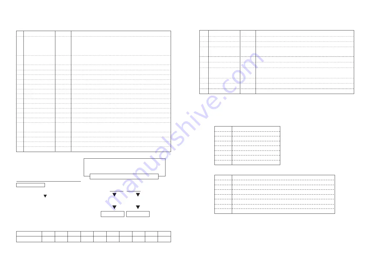
Data Contents (Command 1)
When Control Pack receives a command 1 "$44 $41 $0D", the following data 20 bytes
shall be transmitted.
1
2
3
4
5
6
7
8
9
10
11
12
13
14
15
16
17
18
19
20
$2A
Selector operating
mode
Setting rotation
directions
Setting rpm.
Setting rpm.
Setting rpm.
Rpm
Rpm
Rpm
Motor current value
Motor current value
Motor current value
Motor voltage value
Motor voltage value
Motor voltage value
Error number
Error number
Checksum
Checksum
$0D
10^ 1
10^ 0
10^ ‑1
10^ 1
10^ 0
10^ ‑1
10^ 1
10^ 0
10^ ‑1
10^ 1
10^ 0
10^ ‑1
10^ 1
10^ 0
(H)
(L)
The head of data is shown. It's ASCII code "*".
$31 Panel operation mode
$32 Remote operation mode
$33 Selector operation mode.
$34 Panel/RemoteSelector operating mode.
$30 CW (Forward rotation)
$31 CCW(Reverse rotation)
Two‑digit number of setting rpm. is shown by ASCII code.(unit:kmin ‑1)
One‑digit number of setting rpm. is shown by ASCII code.
1/10‑digit number of setting rpm. is shown by ASCII code.
Two‑digit number of the motor rpm. is shown by ASCII code.(unit:kmin ‑1)
One‑digit number of the motor rpm. is shown by ASCII code.
1/10‑digit number of the motor rpm. is shown by ASCII code.
Two‑digit number of the motor current value is shown by ASCII code.(unit:A)
One‑digit number of the motor current value is shown by ASCII code
1/10‑digit number of the motor current value is shown by ASCII code
Two‑digit number of the motor voltage value is shown by ASCII code(unit:V)
One‑digit number of the motor voltage value is shown by ASCII code
1/10‑digit number of the motor voltage value is shown by ASCII code
Two‑digit number of the error number is shown by ASCII code.
when error has not arisen, it's "00" ($30 $30)
One‑digit number of the error number is shown by ASCII code.
Higher rank checksum data is shown.
Lower rank checksum data is shown.
The last of data is Control Code "CR".
(For checksum calculation method)
From data No.1 to the 17th
「$2A」〜「Error number10^ 0 」
Upper 4 bits Lower 4 bits
「○○○○○・・○○○○ ○○○○ 」
Add "$30" respectively.
←Lower 8 bits
Checksum (H)
Checksum (L)
(Relation between a number and ASCII code)
(Calculation example)
Lower 8 bits of total to the transmitting data
=1011 0101
●Checksum (H)
1011 + $30 = $0B + $30 = $3B
●Checksum (L)
0101 + $30 = $05 + $30 = $35
Number
ASSCII code
0
$30
1
$31
2
$32
3
$33
4
$34
5
$35
6
$36
7
$37
8
$38
9
$39
Transmitting data total
Transmitting data
●
Data Contents (Command 2)
When Control Pack receives a command 2 "$44 $42 $0D", the following data 20 bytes
shall be transmitted.
●
Contents of External Input/Output Signals
The input signal from CONTROL connector is shown in "Chart‑3" and output signal is
shown in "Chart‑4". In the relation between the input signal and the bit value, Bit
is "1" in case of the input signal "ON" and is "0" in case of "OFF".
1
2
3
4〜
6
7
8
9〜
17
18
19
20
$2A
Air pressure
Air pressure
External input signal
External output signal
Checksum
Checksum
$0D
10^ ‑ 1
10^ ‑ 2
(H)
(L)
It is the head of data. It's ASCII code "*".
1/10‑digit number of the air pressure value is shown by ASCII code.(unit:Mpa)
1/100‑digit number of the air pressure value is shown by ASCII code.
Confirming the operation of factory shipment
Refer to Chart‑3 "Contents of External input signal".
Refer to Chart‑4 "Contents of External output signal".
Confirming the operation of factory shipment
Higher rank checksum data of transmitting data is shown.
Lower rank checksum data of transmitting data is shown.
The last of data is Control Code "CR".
External Input Signal
External Output Signal
Bit 7 always 0
Bit 6 always 0
Bit 5 always 1
Bit 4 always 1
Bit 3 always 0
Bit 2 external reset signal
Bit 1 external start signal
Bit 0 external rotation signal
Bit 7 always 0
Bit 6 always 0
Bit 5 always 1
Bit 4 always 1
Bit 3
Motor stop signals "1" during pauses/ "0" be in action
Bit 2
Speed attainment signals "1" attainment / "0" in transit
Bit 1
Motor connection signals "1" normal connection /"0" error
Bit 0
Alarm signals "1" normal operation / "0" error
Chart‑3
Chart‑4
Summary of Contents for SFIDA 01 Series
Page 12: ......


