background image

Capitolo 5. Regolazione ed approntamento macchina 

IT 


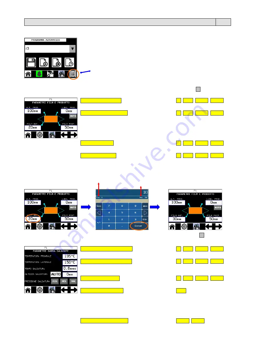
5.2.4. Impostazione dei parametri del PROGRAMMA AUTOMATICO (da tasto “Dati”) 


Premere il tasto “Dati”. 


A questo punto compare la prima videata relativa ai parametri del programma e premendo il tasto  

  si scorrono tutte 

le successive videate:  


ALTEZZA PRODOTTO  

[mm]


56  56CS  56MPE  56MPS 

Regola l’apertura del triangolo. Valori: 35 ÷ 240.  


LUNGHEZZA PRODOTTO  

[mm]


56  56CS  56MPE  56MPS


Se impostata su AUTO la saldatura del film avviene nel momento in cui la fotocellula 
legge la fine del prodotto. Consigliata per prodotti con forma regolare. Se impostata su 
MAN la funzione disattiva la lettura della fine del prodotto mediante fotocellula. In 
questo caso la saldatura avviene impostando la variabile “LUNGHEZZA PRODOTTO”. 
Valori: 1 ÷ 600. 


FILM ANTERIORE  

[mm]


56  56CS  56MPE  56MPS 

Regola la quantità di film che si vuole lasciare davanti al prodotto. Valori: 0 ÷ 300. 


FILM POSTERIORE  

[mm]


56  56CS  56MPE  56MPS


Regola la quantità di film che si vuole lasciare dietro al prodotto. Valori: 0 ÷ 900. 


Per modificare i valori impostati (es. FILM ANTERIORE da 20mm a 30mm) seguire la procedura sotto descritta.  


Indica il valore minimo di impostazione della variabile. 

Indica il valore massimo di impostazione della variabile. 


Premere sul valore numerico  
(es. 20mm). 


Inserire il nuovo valore e premere  
il tasto “Enter”. 


Premere il tasto  

  e scorrere 

le videate successive. 


TEMPERATURA FRONTALE

  [C]  

56  56CS  56MPE  56MPS 

Regola la temperatura della barra saldante frontale (corta). Valori: 0 ÷ 240. 


TEMPERATURA LATERALE

  [C]  

56  56CS  56MPE  56MPS 

Regola la temperatura della barra saldante laterale (lunga).  
Valori: 0 ÷ 240 (Pratika 56, 56CS, 56MPE);  0 ÷ 365 (Pratika 56MPS). 


TEMPO SALDATURA

  [s]  

56  56CS  56MPE  56MPS 

Regola il tempo di saldatura della barra saldante laterale e frontale. Valori: 0 ÷ 3. 


ALTEZZA SALDATURA

  [mm] 

56CS 

Regola la posizione della saldatura rispetto al nastro. Valori: AUTO / MAN. 
Se impostato su AUTO la saldatura avviene a meta dell’altezza del prodotto. Ideale 
per prodotti standard. 
Se impostato su MAN la saldatura avviene alla  misura impostata (misurata partendo 
dal piano del nastro di uscita). Valori: 0 ÷ 120mm.  


PRESSIONE SALDATURA 

56MPE  56MPS


Regola la pressione della barra saldante sul film, per ottimizzarne il taglio.  
Valori: MIN / MED / MAX 


12 

Summary of Contents for MF21BA54

Page 1: ...3BA65 Pratika 56 MPS MF23BA83 MF23BA84 Versione HMI 3 00 HMI 3 00 version Version HMI 3 00 Pratika 56 Pratika 56 CS Pratika 56 MPE Pratika 56 MPS Valido dalla matr Valid from s n Gültig ab Seriennr 1534 07 2014 1525 06 2014 1526 06 2014 1505 04 2014 xxxx xx 2014 IT LEGGERE ATTENTAMENTE QUESTE ISTRUZIONI PRIMA DI USARE LA MACCHINA EN BEFORE USING THE MACHINE PLEASE CAREFULLY READ THE INSTRUCTIONS D...

Page 2: ...ei parametri del PROGRAMMA AUTOMATICO da grafico 16 5 2 6 Scelta del programma AUTOMATICO 17 5 2 7 Impostazione dei parametri del PROGRAMMA MANUALE 18 5 2 8 Cancellazione di un programma 19 5 2 9 Scelta della lingua 19 5 2 10 Tempo di pausa 19 5 2 11 Contatore parziale e contatore lotto 20 5 2 12 Backup programmi 20 5 3 Allarmi 21 5 4 Inserimento del film 23 5 5 Regolazioni 26 5 5 1 Regolazione de...

Page 3: ...ffidata ad un operatore addetto conduttore questi dovrà essere abilitato ad eseguire tutte le operazioni inerenti il processo operativo inoltre deve poter segnalare al personale addetto manutentore o tecnico dell assistenza esterna eventuali guasti o anomalie La macchina lavora in modalità AUTOMATICO Essa è gestita da un logica di controllo presente nel PLC di comando Grazie alla propria versatili...

Page 4: ...0mm Pratika 56 CS a 600mm b 400mm c 240mm Pratika 56 MPE a 600mm b 400mm c 240mm Pratika 56 MPS a illimitata b 400mm c 240mm Nota le misure indicate nella tabella si riferiscono alla misura max della singola dimensione Per la misura max della confezione b x c bisogna comunque fare riferimento al capitolo 2 2 dove si vede che la somma di b c è comunque uguale alla larghezza della bobina del film me...

Page 5: ... sicurezza È vietato eseguire modifiche alla macchina senza l autorizzazione del costruttore Se il cavo di alimentazione è danneggiato esso deve essere sostituito dal costruttore o dal suo servizio assistenza tecnica o comunque da una persona con qualifica similare in modo da prevenire ogni rischio Il quadro elettrico durante il funzionamento deve sempre rimanere chiuso La chiave per aprire il qua...

Page 6: ...lle zone interessate predisporre la macchina per la messa in stato di manutenzione quindi attendere il raffreddamento delle resistenze Non eseguire nessuna operazione senza avere indossato i dispositivi di protezione quali guanti e camice Pericolo di folgorazione Gruppo di saldatura rischio dovuto all energia elettrica all interno del gruppo di saldatura solo per Pratika 56 MPS Quadro elettrico ri...

Page 7: ... 2 pulsanti arresta immediatamente la macchina in caso di pericolo immediato o per la messa in stato di manutenzione Se premuti per sbloccarli occorre girarli in senso orario S2 Pulsante RESET Da premere all accensione della macchina Ripristina la macchina dopo l intervento del pulsante EMERGENZA e dell allarme A001 S3 Selettore ESCLUSIONE SICUREZZA Se posizionato su OFF consente l uso della macch...

Page 8: ...ckup ripristino programmi USB Diagnosi PLC Impostazione visualizzazione parametri da Grafico scelta rapida parametri Salva programma Impostazione visualizzazione parametri da Dati Carica programma Pagina precedente Cancella programma Pagina successiva Nuovo programma Login autenticazione utente Movimentazione nastri ed esecuzione trascinamento svolgitore avvogitore film Logout Saldatura Gestione u...

Page 9: ... Automatico Rosso Si Verde Verde 5 2 Avviamento Ruotare l interruttore generale Q1 nella posizione 1 e premere il pulsante RESET S2 Il display si accende e compare la videata con il logo minipack torre Premere sul logo Successivamente compare la videata principale All accensione della macchina vedrete lampeggiare i numeri che indicano la temperatura della barra saldante frontale e laterale Raggiun...

Page 10: ...ndo il selettore a chiave S3 nella pos ON Il pulsante Allarme è rosso in quanto è attivo l allarme A002 RIPARI APERTI Ruotando il selettore S3 nella pos OFF l allarme si resetta e il pulsante diventa verde Premendo il tasto START si passa allo STATO START Manuale e si abilita il funzionamento del nastro espulsione dell ultimo prodotto e funzionamento della saldatura AUTO MAN Premendo su questo tas...

Page 11: ...nutentore e Fabbrica secondo e terzo livello Menù protetto da password Fabbrica terzo livello Menù protetto da password Manutentore secondo livello Sblocco Password Operatore primo livello Per sbloccare la Password l operatore deve conoscere il Nome e la Password di primo livello Il simbolo del lucchetto accanto ad un qualunque tasto indica che questa funzione è protetta da Password Per lo sblocco...

Page 12: ...e il tasto Main È ricomparso il simbolo del lucchetto che indica la protezione tramite password 5 2 3 Creazione di un nuovo PROGRAMMA AUTOMATICO La macchina lavora normalmente in ciclo automatico La macchina viene fornita con un programma automatico P1 già memorizzato ma con parametri standard Prima di confezionare un prodotto si consiglia di creare un nuovo programma con le impostazioni specifich...

Page 13: ...er modificare i valori impostati es FILM ANTERIORE da 20mm a 30mm seguire la procedura sotto descritta Indica il valore minimo di impostazione della variabile Indica il valore massimo di impostazione della variabile Premere sul valore numerico es 20mm Inserire il nuovo valore e premere il tasto Enter Premere il tasto e scorrere le videate successive TEMPERATURA FRONTALE C 56 56CS 56MPE 56MPS Regol...

Page 14: ...i volta che si carica questo programma potete applicare quanto memorizzato POSIZIONE ROTELLE TENDIFILM SU TRIANGOLI 56 56CS 56MPE 56MPS Inserire la posizione delle rotelle R6 OPTIONAL facendo riferimento alla scala millimetrata X3 vedi paragrafo 5 4 FASE 6 La funzione può essere ON solo se abilitata negli OPTIONAL ATTIVAZIONE SOFFIO ARIA 56 56CS 56MPE 56MPS Indicare se per questo programma è appli...

Page 15: ...ORATORI 56 56CS 56MPE 56MPS Inserire il numero di microforatori MF da posizionare sulla macchina vedi paragrafo 5 4 FASE 6 POSIZIONE BOBINA FILM mm 56 56CS 56MPE 56MPS Inserire la posizione della bobina di film facendo riferimento alla scala millimetrata X1 vedi paragrafo 5 4 FASE 6 POSIZIONE RULLO RINVIO FILM mm 56 56CS 56MPE 56MPS Inserire la posizione del rullo di rinvio R5 facendo riferimento ...

Page 16: ...tà del nastro di uscita OUT Valori 100 130 La funzione è attiva solo se abilitata negli OPTIONAL UTILIZZO NASTRO SCARICO 56 56CS 56MPE 56MPS Se impostato su OFF disabilità il fuzionamento del nastro di scarico Valori ON OFF PEDALE 56 56CS 56MPE 56MPS La funzione permette di avviare il nastro di carico con il comando a pedale OPTIONAL e fermarlo dopo lo scarico del pezzo per agevolare la composizio...

Page 17: ...o visto come è possibile visualizzare impostare i parametri di un programma automatico mediante il tasto Dati Nella schema di seguito è spiegato un altro metodo che permette di visualizzare impostare i soli parametri che si desidera senza dover scorrere tutte le videate Questo è possibile selezionando sul grafico della macchina la zona interessata 16 ...

Page 18: ...ina Premere il tasto CONTINUA La prima videata vi ricorda i dati con le impostazioni manuali da eseguire sulla Pratika 56 numero dei microforatori da utilizzare posizionamento della bobina di film posizionamento del rullino rinvio posizionamento delle rotelle tendifilm eventuale attivazione del soffio d aria Premere il tasto IMPOSTAZIONI TUNNEL questa videata compare solo se nel menù CONFIGURAZION...

Page 19: ...gola la velocità dei nastri d ingresso IN e di uscita OUT da 6m min a 30m min La velocità dei nastri è identica per entrambi Valori 20 100 PRESSIONE SALDATURA 56MPE 56MPS Regola la pressione della barra saldante sul film per ottimizzarne il taglio Valori MIN MED MAX FUNZIONE NASTRO TRASPORTO 56 56CS 56MPE 56MPS È la condizione di utilizzo in cui la macchina funziona come un semplice nastro traspor...

Page 20: ...rammare il tempo di pausa della macchina Durante questa fase si spengono le resistenze delle barre saldanti condizione che garantisce un notevole risparmio energetico ma rimangono attive tutte le altre funzioni della macchina Questa funzione è utile quando si desidera spegnere le resistenze per un determinato tempo terminato il quale si riattiva il riscaldamento delle stesse per fare un esempio qu...

Page 21: ...e il tasto Enter Numero prodotti da confezionare lotto Numero prodotti confezionati da quando la macchina è stata accesa Pulsante di RESET contatore parziale Numero prodotti confezionati in totale dalla macchina non modificabile Premere il tasto Main Nota quando è attiva la funzione del numero di prodotti da confezionare lotto il tasto Contatore prodotti lampeggia Una volta confezionati il numero ...

Page 22: ...M ESAURITO A014 AVVOLGITORE ROTTURA FILM A015 NASTRO OUT MANCA CONSENSO DA LINEA A017 SBOBINATORE TIME OUT A018 TIMEOUT MOVIMENTO ROTELLE A019 ERRORE DRIVE A020 ERRORE INVERTER A021 HOMING TIME OUT A022 MANUTENZIONE IN CORSO A023 NASTRO CARICO VUOTO A024 MACCHINA IN RISCALDAMENTO si ripristina con il raggiungimento della temperatura impostata A025 NUMERO LOTTO RAGGIUNTO A027 FOTOCELLULE TIME OUT A...

Page 23: ...dell allarme A002 RIPARI APERTI vedrete lampeggiare il pulsante RESET S2 La procedura per il ripristino di questo allarme è la seguente Chiudere il riparo Premere il pulsante RESET S2 La macchina è dotata di un PULSANTE DI EMERGENZA S1 che premuto la blocca istantaneamente fermando il ciclo di lavoro La procedura per il ripristino di questo allarme è la seguente Rimuovere la causa dell allarme Sbl...

Page 24: ...oduzione del film premere il pulsante che trovate alla destra della bobina Tenendo premuto il pulsante si aziona il rullo motorizzato su cui appoggia la bobina rilasciando la quantità di film necessaria Inserire i due lembi del film uno sopra e uno sotto il triangolo di guida superiore Ts Afferrare le due estremità del film e svolgere per circa 1 metro FASE 2 Prendere il lato inferiore del film in...

Page 25: ...ssario chiudere i ripari anteriore C1 e posteriore C2 Infine annodare il film sul perno presente sulla flangia posteriore F FASE 5 Pratika 56 MPS Appoggiare l estremità del film tra le due ruote R4 del trascinatore A questo punto tenendo premuto il tasto Movimentazione nastri il film viene trascinato all interno del gruppo dove avviene la saldatura del film Premere il tasto Movimentazione nastri f...

Page 26: ...lino di rinvio R5 Vedi scala millimetrata X2 Posizionare le rotelle tendifilm R6 OPTIONAL sui triangoli Vedi scala millimetrata X3 FASE 7 Regolare quindi le aste di posizionamento B agendo sulle manopole M3 in modo da bloccare la bobina lasciando 5 mm di spazio tra le aste e la bobina Nota Il corretto posizionamento della bobina si ha quando stando dietro alla macchina il lato sinistro del film si...

Page 27: ...a macchina è predisposta per il posizionamento della fotocellula a lettura verticale B5 indicata per i prodotti particolarmente bassi e della fotocellula orizzontale B6 indicata per i prodotti particolarmente stretti E possibile inoltre regolare la distanza della fotocellula dalla barra saldante in modo da ottimizzare l inserimento dei prodotti 5 5 3 Regolazione astina di sollevamento film L astin...

Page 28: ...ragrafo 5 4 FASE 1 5 6 Confezionamento Eseguite tutte le regolazioni la macchina é pronta per procedere al confezionamento Con la macchina in stato STOP Automatico premere il pulsante START I nastri entreranno in funzione ed è possibile posizionare i prodotti sul nastro di ingresso Con il passaggio del prodotto sul nastro di uscita il telaio saldante si abbassa per realizzare la saldatura del film...

Page 29: ... contatto col film utilizzando stracci o carta Non utilizzare oggetti che possano danneggiarne la superficie Ogni 12 mesi Supporti Effettuare la lubrificazione con grasso tipo NLGI 2 Ogni 12 mesi Accoppiamenti tra ingranaggi Controllare la presenza di grasso lubrificante Ogni 3 mesi Lame e barre di contrasto Controllare lo stato di usura del teflon adesivo e della piattina in silicone AVVERTENZA I...

Page 30: ...ostituzione o riparazione gratuita di tutte quelle parti riscontrate da noi difettose per anomalie di materiali Le riparazioni o sostituzioni avvengono normalmente presso la casa costruttrice con l addebito all acquirente delle spese di trasporto o manodopera Qualora le riparazioni o sostituzioni vengano eseguite presso la sede dell acquirente quest ultimo sarà tenuto a pagare le spese di viaggio ...

Page 31: ...settings for the AUTOMATIC PROGRAM from graphic 45 5 2 6 Choosing the AUTOMATIC program 46 5 2 7 Parameter settings for the MANUAL PROGRAM 47 5 2 8 Deleting a program 48 5 2 9 Choose the language 48 5 2 10 Pause time 48 5 2 11 Partial and stock counter 49 5 2 12 Backup programs 49 5 3 Alarms 50 5 4 Introducing of the film 52 5 5 Adjustments 55 5 5 1 Adjusting the infeed belt 55 5 5 2 Adjusting the...

Page 32: ...c using single fold heat shrink film The machine can be fed manually or operate in series with other machinery If it is fed by a qualified technician machine operator he needs to be instructed accordingly and he has to be able to advise it can maintenance technician in case of malfunctions or machine anomalies Operate in AUTOMATIC mode The machine is managed by a control logic housed in the PLC Th...

Page 33: ... Max pack sizes Pratika 56 a 600mm b 400mm c 160mm Pratika 56 CS a 600mm b 400mm c 240mm Pratika 56 MPE a 600mm b 400mm c 240mm Pratika 56 MPS a unlimited b 400mm c 240mm Note measurements shown refer to the maximum for the single dimension Refer to chapter 2 2 to get max dimension of pack b x c the addition of b c is equal to film roll width minus 100mm 3 2 Items that may be packaged These machin...

Page 34: ...achine without prior authorisation from the manufacturer If the supply cord is damaged it must be replaced by the manufacturer its service agent or similarly qualified persons in order to avoid a hazard The electrical enclosure must remain closed during operation The key to open the electrical enclosure must be kept by a specialised and authorised member of personnel Smoking is forbidden while the...

Page 35: ...forming operations in these zones set the machine to maintenance mode and wait for resistances to cool Never perform operations without suitable personal protective equipment such as gloves and overalls Electric shock hazard Sealing unit risk due to electric energy inside sealing unit Pratika 56 MPS only Electric control board risk due to electric energy inside electrical control board in terminal...

Page 36: ...diate danger or to place it in maintenance conditions If they are pressed they need to be turned clockwise to release them S2 Button RESET Press when starting up the machine Reset the machine after the EMERGENCY pushbutton and the A001 alarm have been activated S3 BYPASS SAFETY PROTECTIONS selector If this selector switch is set to OFF the machine may only be operated if the guards are closed AUTO...

Page 37: ... information Program backup restore USB PLC diagnosis Parameter setting display from Graph quick selection parameters Save program Parameter setting display from Data Load program Previous page Delete program Next page New program Login user authentication Conveyor belt movement and execution of film feed winder unwinder Logout Sealing Users and password management Product ejection Choosing the la...

Page 38: ...Yellow Roll end in Automatic Start Red Yes Green Green 5 2 Start up Turn the main switch Q1 into pos 1 and press the RESET S2 button The display switches on and the screen with the minipack torre logo appears Press the logo The main screen is displayed When the machine is switched on the numbers that indicate the temperature of the front and side sealing bars start flashing Once the bars have reac...

Page 39: ...ng the selector key S3 to the ON position The Alarm button is red since the A002 OPEN GUARDS alarm is active By turning the selector S3 to the OFF position the alarm resets itself and the button becomes green Press the START button to switch to CONDITION Manual START and enable the belt expulsion of the last product and the sealing function AUTO MAN Press this button to alternate between the MANUA...

Page 40: ...st level Maintenance technician and Factory Passwords second and third levels Menu protected by Factory password third level Menu protected by Maintenance technician password second level Operator Password Release first level The operator must know the first level Name and Password to release the Password The padlock symbol next to a key indicates the function is Password protected To unlock it fo...

Page 41: ...button and then the button Main The padlock symbol has re appeared indicating that the programme is protected with a password 5 2 3 Creation of a new AUTOMATIC PROGRAM The machine normally works in automatic cycle The machine is provided with an already memorised automatic program P1 but with standard parameters We recommend creating a new program with the specific settings for your product before...

Page 42: ... of film to leave behind the pack Values 0 900 To modify the set values e g FRONT FILM from 20mm to 30mm follow the procedure below Indicates the minimum variable setting Indicates the maximum variable setting Press the numerical value e g 20 Enter the new value and press Enter Press and scroll the next screens FRONT TEMPERATURE C 56 56CS 56MPE 56MPS Adjusts the front bar short sealing temperature...

Page 43: ...ngs can be applied POSITION FILM TENSIONING ROLLERS ON TRIANGLES 56 56CS 56MPE 56MPS Enter the position of the wheels R6 OPTIONAL with reference to the millimetre scale X3 see paragraph 5 4 PHASE 6 The function can be ON only if it is enabled in OPTIONALS BLOW AIR ACTIVATION 56 56CS 56MPE 56MPS Indicate whether the AIR BLOW kit is applied ON or not OFF for this program Values ON OFF The function c...

Page 44: ...ised settings can be applied NUMBER OF MICROPUNCHES 56 56CS 56MPE 56MPS Enter the number of micro punches MF to be positioned on the machine see paragraph 5 4 PHASE 6 FILM REEL POSITION 56 56CS 56MPE 56MPS Enter the film reel position with reference to the millimetre scale X1 see paragraph 5 4 PHASE 6 FILM DRIVING ROLL POSITION 56 56CS 56MPE 56MPS Enter the position of the return roller R5 with re...

Page 45: ...lt speed with regard to the speed of the outfeed belt OUT Values 100 130 The function is only active if it is enabled in OPTIONALS UNLOAD BELT USE 56 56CS 56MPE 56MPS If set to OFF it disables the unload belt operation Values ON OFF PEDAL 56 56CS 56MPE 56MPS This function enables the operator activate the load belt using the pedal control OPTIONAL when processing multiple packages Values ON OFF Th...

Page 46: ...e seen how it is possible to view set the parameters for an automatic program by means of the Data key Another method is explained in the following diagram which enables you to view set only the desired parameters without having to scroll through all the screens This is possible by selecting the relevant area from the machine s graphic 45 ...

Page 47: ...tings to apply to the machine Press CONTINUE The first screen reminds you of the data with the manual settings to run on the Pratika 56 number of micro punches to use positioning of the film reel positioning of the return roller positioning of the film roller wheels any activation of the air blow Press TUNNEL SETTINGS this screen only appears if the Tunnel coupled with the machine was selected in ...

Page 48: ...lt OUT speeds from 6m min to 30m min Belt speed is identical for both Values 20 100 SEALING PRESSURE 56MPE 56MPS Regulates the pressure of the film sealing bar to optimise the cut Values MIN MED MAX CONVEYOR BELT FUNCTION 56 56CS 56MPE 56MPS It is the condition of use in which the machine works as a conveyor belt The belts convey the products from the infeed area to the outfeed area without being ...

Page 49: ...unction is used to programme the machine s pause time During this phase the sealing bar resistors switch off a condition that ensures considerable energy savings while all of the other machine functions stay on This function is useful when you wish to switch off the resistors for a given amount of time and when said amount of time has elapsed they will heat up again for example this function is ve...

Page 50: ...er of products stock to be packaged Press Enter Number of products to pack batch Number of products packed since the machine was switched on Partial count RESET button Number of products packed in total by the machine cannot be changed Press the Main button Note when the number of products to package batch function is active the Product counter key flashes Once the machine has packaged the program...

Page 51: ...3 UNWINDER FILM FINISHED A014 REWINDER BROKEN FILM A015 NO LINE AT OUTFEED CONVEYOR A017 UNWINDER TIME OUT A018 WHEEL MOVEMENT TIMEOUT A019 DRIVE ERROR A020 INVERTER ERROR A021 HOMING TIME OUT A022 ON MAINTENANCE A023 LOAD BELT EMPTY A024 MACHINERY WARMING this is reset when the machine reaches the programmed temperature A025 STOCK OF MANUFACTURES ENDED A027 PHOTOCELLS TIME OUT A028 WHEEL MOVEMENT...

Page 52: ...en reset Note in the case of the A002 OPEN GUARDS alarm only the RESET S2 button starts flashing To reset this alarm proceed as follows Close the guard Press the RESET S2 button The machine is fitted with EMERGENCY Pushbutton S1 that stop the machine instantaneously when pressed interrupting the work cycle To reset this alarm proceed as follows Remove the cause of the alarm Release the EMERGENCY P...

Page 53: ...oduce the film press the button on the right of the reel Press and hold this button to activate the motorised roller that the reel rests on in order to release the required quantity of film Insert the two film flaps one above and one below the upper guide triangle Ts Grasp the two ends of the film and unwind about 1 metre PHASE 2 Take the lower edge of the film corresponding to the rear edge of th...

Page 54: ...der to seal the film you must close the front C1 and back C2 guards Lastly tie the film onto the pin attached to the rear flange F PHASE 5 Pratika 56 MPS Place the end of the film between the two wheels R4 of the dragging device Been holding the Conveyor belt movement key pressed the film is drawn inside the unit where it is sealed Press the Conveyor belt movement key until a sufficient strip of f...

Page 55: ...roller R5 See millimetric scale X2 Position the film roller wheels R6 OPTIONAL on the triangles See millimetric scale X3 PHASE 7 Next adjust the positioning bars B regulating the knob M3 in order to lock the reel and leaving a gap of 5 mm between the bars and the reel Note The reel is positioned correctly when the left edge of the film viewed from the rear of the machine is at a distance A equival...

Page 56: ...g the photocells The machine is set up for the positioning of the vertical reading photocell B5 recommended for extra low products and the horizontal photocell B6 recommended for extra narrow products It is also possible to modify the distance between photocell and the sealing bar in order to optimise the way the products are inserted 5 5 3 Adjusting the film raiser bar The bar A is used to raise ...

Page 57: ...aragraph 5 4 PHASE 1 5 6 Packaging Once all adjustments have been made the machine is ready to start working With the machine in condition Automatic STOP press the START key The belts will begin operating and it is possible to place the products on the infeed belt When the product travels along the outfeed belt the sealing frame descends to seal the film The packaged product advances towards the r...

Page 58: ...ration Every day Blades Clean surfaces that come into contact with the film using cloths or paper Never use objects that may damage the surfaces Every 12 months Supports Carry out lubrication with grease type NLGI 2 Every 12 months Gear couplings Ensure sufficient lubrication Every 3 months Blades and contrast bars Check the condition of the adhesive teflon strips and silicon plate WARNING Gears r...

Page 59: ...force on the installation date of the machine The guarantee covers free replacement or repair of any parts due to defects arising from faulty material The repairs or replacement are usually carried out at the manufacturer s premises with transport or labour charged to the buyer If the repair or replacement is carried out at the buyer s premises he shall bear the travelling transfer and labour cost...

Page 60: ...RAMMS mit der Taste Daten 70 5 2 5 Einstellung der Parameter des AUTOMATIKPROGRAMMS über Diagramm 74 5 2 6 Auswahl des AUTOMATIKPROGRAMMS 75 5 2 7 Einstellung der Parameter des MANUELLEN PROGRAMMS 76 5 2 8 Löschen eines Programms 77 5 2 9 Sprachwahl 77 5 2 10 Wartezeit 77 5 2 11 Teilzähler und Chargenzähler 78 5 2 12 Backup Programme 78 5 3 Alarme 79 5 4 Einsetzen der Folie 81 5 5 Einstellungen 84...

Page 61: ...tändigen Bediener Maschinenführer überlassen wird muss dieser dazu befähigt sein alle Arbeiten auszuführen die den Betriebsprozess betreffen außerdem muss er dem zuständigen Personal Wartungstechniker oder Techniker des Kundendienstes mögliche Defekte oder Störungen mitteilen können Die Maschine arbeitet im AUTOMATIKBETRIEB Sie wird von einer Steuerungslogik verwaltet die sich in der Steuerungs SP...

Page 62: ...imale Abmessungen der Packung Pratika 56 a 600mm b 400mm c 160mm Pratika 56 CS a 600mm b 400mm c 240mm Pratika 56 MPE a 600mm b 400mm c 240mm Pratika 56 MPS a Unbegrenzt b 400mm c 240mm Hinweis Die in der Tabelle angegebenen Maβe beziehen sich auf die max Größe der einzelnen Packung Was die Höchstmaße der Packung b x c betrifft beziehen Sie sich bitte in jedem Fall auf das Kapitel 2 2 aus dem herv...

Page 63: ...Veränderungen an den Sicherheitsvorrichtungen und kreisen vorzunehmen Es ist verboten ohne Erlaubnis des Herstellers Änderungen an der Maschine vorzunehmen Wenn das Stromversorgungskabel beschädigt ist muss es vom Hersteller oder von dessen Kundendienst ausgewechselt werden oder zumindest von einer Person mit gleichwertiger Qualifikation um jegliche Gefahr zu meiden Die Schalttafel muss während de...

Page 64: ...ahr besteht durch Erhitzen der Folienschweißmesser Bevor auf diesen Bereich eingegriffen werden kann muss die Maschine in den Wartungszustand gebracht werden und die Widerstände müssen sich abkühlen Keine Arbeiten ohne Schutzkleidung wie Handschuhe und Kittel durchführen Gefahr eines Stromschlags Schweißgruppe Risiko durch elektrischen Strom im Innern der Schweißgruppe Nur für Pratika 56 MPS Schal...

Page 65: ...ittelbar bevorstehender Gefahr oder Versetzung in den Wartungsstatus sofort an Um sie wenn sie gedrückt sind freizugeben dieselben im Uhrzeigersinn drehen S2 Taste RESET Ist bei der Start der Maschine zu drücken Stellt die Maschine nach Anspringen der NOTTASTE und des Alarms A001 wieder zurück S3 Wahlschalter SICHERHEITEN AUS Bei OFF Stellung ist der Maschinengebrauch nur mit geschlossenen Schutzv...

Page 66: ...ormation Datensicherung Rückstellung Programme USB Diagnose PLC Einstellung Anzeige Parameter über Diagramm Kurzwahl Parameter Programm speichern Einstellung Anzeige Parameter über Daten Programm laden Vorhergehende Seite Programm löschen Nächste Seite Neues Programm Login Authentifizierung Benutzer Bewegung Bänder und Durchführung Transport Folienabwickler Folienaufwickler Logout Schweißung Verwa...

Page 67: ...Ja Grün Grün 5 2 Start Den Hauptschalter Q1 in die Position 1 drehen und die Taste drücken RESET S2 Das Display schaltet sich ein es wird der Bildschirm mit dem Logo minipack torre angezeigt Das Logo antippen Danach erscheint die Hauptseite Bei der Einschaltung der Maschine blinken die Zahlen die die Temperatur des frontalen und seitlichen Schweißbalkens anzeigen Nach Erreichung der im geladenen P...

Page 68: ...öffnet werden Die Taste der Alarm ist rot da der Alarm A002 GEÖFFNETE SCHUTZEINRICHTUNGEN aktiviert ist Durch Drehen des Schlüsselwahlschalters S3 in Pos OFF wird der Alarm rückgestellt und die Taste wird grün Wenn Sie die Taste START drücken wechseln Sie in den ZUSTAND Manueller START und der Betrieb des Bands der Ausstoß des letzten Produkts und der Betrieb der Schweißung werden aktiviert AUTO M...

Page 69: ... Werk zweite und dritte Ebene Menü Werk passwortgeschützt dritte Ebene Menü Wartungstechniker passwortgeschützt zweite Ebene Freigabe Passwort Bediener erste Ebene Für die Freigabe des Passwortes muss der Bediener den Namen und das Passwort der ersten Ebene kennen Das Symbol des Schlosses neben einem beliebigen Text zeigt an dass diese Funktion durch Passwort geschützt ist Für die Freigabe die unt...

Page 70: ...s Symbol das anzeigt dass das Programm passwortgeschützt ist 5 2 3 Erstellung eines neuen AUTOMATIKPROGRAMMS Normalerweise arbeitet die Maschine im Automatikzyklus Die Maschine wird mit einem bereits gespeicherten Automatikprogramm P1 geliefert aber mit Standardparametern Vor dem Verpacken von einem Produkt empfehlen wir ein neues Programm mit den spezifischen Einstellungen für das jeweilige Produ...

Page 71: ...erändern z B VORDERE FOLIE von 20mm bis 30mm die nachfolgend beschriebene Prozedur ausführen Gibt den Mindestwert für die Variable an Gibt den Höchstwert für die Variable an Drücken Sie auf den Zahlenwert z B 20 Den neuen Wert eingeben und die Taste Enter drücken Die Taste drücken und die nachfolgende Bildschirmseite durchblättern TEMPERATUR FRONTAL C 56 56CS 56MPE 56MPS Regelt die Temperatur des ...

Page 72: ...ieses Programm geladen wird die gespeicherte Einstellung angewendet werden kann POSITION FOLIENSPANNERRÄDCHEN AN DREIECKEN 56 56CS 56MPE 56MPS Die Position der Rädchen R6 OPTIONAL mit Bezug auf die metrische Skala X3 eingeben siehe Abschnitt 5 4 PHASE 6 Die Funktion kann nur dann ON sein wenn sie in den OPTIONALs vorgesehen ist AKTIVIERUNG LUFTSTROM 56 56CS 56MPE 56MPS Angeben ob für dieses Progra...

Page 73: ...RER 56 56CS 56MPE 56MPS Die Anzahl der Mikroperforationsvorrichtungen MF eingeben die an der Maschine positioniert werden sollen siehe Abschnitt 5 4 PHASE 6 POSITION FOLIENSPULE mm 56 56CS 56MPE 56MPS Die Position der Folienspule mit Bezug auf die metrische Skala X1 eingeben siehe Abschnitt 5 4 PHASE 6 POSITION UMLENKROLLE FOLIE mm 56 56CS 56MPE 56MPS Die Position der Umlenkrolle R5 mit Bezug auf ...

Page 74: ...indigkeit des Auslaufbandes OUT Werte 100 130 Die Funktion ist nur aktiviert wenn sie in den OPTIONALs vorgesehen ist GEBRAUCH DES ENTLADEBANDES 56 56CS 56MPE 56MPS Wenn auf OFF eingestellt wird der Betrieb des Entladebandes deaktiviert Werte ON OFF PEDAL 56 56CS 56MPE 56MPS Durch diese Funktion kann das Transportband mit einem Pedal OPTIONAL gestartet und nach Verpackung des Produkts abgeschaltet...

Page 75: ...t wie die Parameter eines Automatikprogramms mit der Taste Daten angezeigt eingestellt werden können Im nachfolgendem Schema wird eine andere Möglichkeit aufgeführt wie nur die gewünschten Parameter angezeigt eingestellt werden können und ohne dass alle Bildschirmseiten durchblättert werden müssen Dazu wird im Diagramm der Maschine die betreffende Zone ausgewählt 74 ...

Page 76: ...aste WEITER drücken Auf der ersten Bildschirmseite können die Daten mit den manuellen Einstellungen die an der Pratika 56 ausgeführt werden sollen abgerufen werden Anzahl der zu verwendenden Mikroperforationsvorrichtungen Positionierung der Folienspule Positionierung der Umweltrolle Position der Folienspannerrädchen Eventuell Aktivierung des Luftstroms Die Taste EINSTELLUNGEN TUNNEL drücken diese ...

Page 77: ... 56MPE 56MPS Regelt die Geschwindigkeit des Einlaufbandes IN und des Auslaufbandes OUT von 6m min bis 30m min Die Bandgeschwindigkeit ist für beide identisch Werte 20 100 VERSIEGELUNGSDRUCK 56MPE 56MPS Reguliert den Druck des Schweißbalkens auf die Folie um den Schnitt zu optimieren Werte MIN MED MAX FUNKTION FÖRDERBAND 56 56CS 56MPE 56MPS Dabei handelt es sich um den Gebrauchszustand in dem die M...

Page 78: ...ren Während dieser Phase schalten sich die Widerstände der Schweißbalken ab Status der eine bemerkenswerte Energieeinsparung garantiert alle anderen Maschinenfunktionen bleiben eingeschaltet Diese Funktion ist nützlich wenn die Widerstände für einen bestimmten Zeitraum abgeschaltet werden sollen nachdem dieser abgelaufen ist schaltet sich die Erwärmung derselben wieder ein diese Funktion ist um ei...

Page 79: ... die Taste Enter Anzahl der zu verpackenden Produkte Los Anteil der verpackten Produkte seit die Maschine eingeschaltet wurde RESET Taste Teilzähler Anzahl der insgesamt von der Maschine verpackten Produkt nicht veränderbar Drücken Sie die Taste Main Hinweis Wenn die Funktion der Anzahl der zu verpackenden Produkte Charge aktiviert ist blinkt der Produktzähler Sobald die eingestellte Anzahl der St...

Page 80: ...CKLER SPULE GEHT ZU ENDE A013 ABWICKLER FOLIE ZU ENDE A014 AUFWICKLER FOLIE GERISSEN A015 AUSLAUFBAND KEINE FREIGABE VON DER LINIE A017 ABROLLER TIME OUT A018 TIMEOUT BEWEGUNG RÄDCHEN A019 ERROR DRIVE A020 INVERTERFEHLER A021 TIME OUT HOMING A022 WARTUNG LÄUFT A023 LADEBAND LEER A024 MASCHINE HEIZT AUF wird nach Erreichen der eingestellten Temperatur zurückgestellt A025 CHARGENZAHL ERREICHT A027 F...

Page 81: ...TE SCHUTZVORRICHTUNGEN blinkt die RESET Taste S2 Für das Rücksetzen dieses Alarms auf folgende Weise vorgehen Schutzvorrichtung schließen Die RESET Taste S2 drücken Die Maschine ist mit einem NOT AUS TASTER S1 ausgestattet der falls er gedrückt wird die Maschine augenblicklich sperrt und den Betriebszyklus stoppt Zur Rückstellung dieses Alarms auf folgende Weise vorgehen Die Alarmursache beseitige...

Page 82: ...hema auf der Abbildung einführen Für ein einfacheres Einlegen der Folie die Taste rechts der Rolle drücken Die Taste gedrückt halten die motorisierte Rolle auf der die Rolle aufliegt wird angetrieben und gibt die erforderliche Folienmenge aus Die beiden Folienseiten über und unter das obere Führungsdreieck Ts einsetzen Die Folie an beiden Enden festhalten und zirka 1 Meter ausrollen PHASE 2 Die un...

Page 83: ...ssen die vorderen C1 und hinteren C2 Schutzvorrichtungen geschlossen werden Dann die Folie am Zapfen des hinteren Flansches F verknoten PHASE 5 Pratika 56MPS Das Ende der Folie zwischen die beiden Walzen R4 des Mitnehmers legen Dann die Taste Bänder gedrückt halten worauf die Folie ins Innere der Gruppe gezogen wird in der das Verschweißen der Folie erfolgt Die Taste Bänder drücken bis ein Foliens...

Page 84: ...onieren Siehe Millimeterskala X2 Die Folienspannerrädchen R6 OPTIONAL an den Dreiecken positionieren Siehe Millimeterskala X3 PHASE 7 Schließlich die Positionierungsstäbe B einstellen Dazu die Knöpfe M3 so betätigen dass die Rolle blockiert wird und ein Freiraum von 5 mm zwischen den Stäben und der Rolle belassen bleibt Hinweis Die Rolle ist dann korrekt positioniert Ansicht von der Rückseite der ...

Page 85: ...ie Maschine ist für die Positionierung der Fotozelle für die vertikale Ablesung B5 vorbereitet die sich für besonders niedrige Produkte eignet und der horizontalen Fotozelle B6 die sich für besonders schmale Produkte eignet Es kann weiterhin der Abstand zwischen der Photozelle auf der Schweissleiste eingestellt werden um die Produkteinführung zu optimieren 5 5 3 Einstellung des Stabs zum Heben der...

Page 86: ... Abschnitt 5 4 PHASE 1 5 6 Verpacken Wenn alle Einstellungen vorgenommen wurden ist die Maschine bereit um mit dem Verpacken zu beginnen Mit der Maschine in Zustand Autom STOPP die Taste START drücken Die Bänder nehmen den Betrieb auf und die Produkte können auf dem Eingangsband abgelegt werden Wenn das Produkt auf das Ausgangsband geleitet wird senkt sich der Schweißrahmen um die Folie zu schweiß...

Page 87: ... Fläche die mit der Folie in Berührung kommt mit Lappen oder Papier Verwenden Sie keine Werkzeuge die die Fläche beschädigen könnten Alle 12 Monate Halterungen Träger Schmieren Sie die Elemente mit Fett vom Typ NLGI 2 Alle 12 Monate Kupplungen zwischen den Zahnrädern Überprüfen Sie ob genügend Schmierfett vorhanden ist Alle 3 Monate Klingen und Gegendrähte Überprüfen Sie den Verschleißgrad des Kle...

Page 88: ...n kostenlosen Austausch oder die Reparatur all jener Teile die wir aufgrund von Werkstoffanomalien als fehlerhaft einstufen Die Reparaturen bzw der Austausch werden normalerweise im Werk des Herstellers vorgenommen wobei der Käufer die Transportkosten und den Arbeitslohn trägt Sollte die Reparatur oder der Austausch beim Käufer vorgenommen werden so trägt dieser die Reisekosten das Tagegeld und de...

Page 89: ...s disposições pertinentes das directrizes aplicáveis CS splňuje základní požadavky na bezpečnost a všechna příslušná ustanovení platných směrnic NL conform is met de essentiële veiligheidsvereisten en met alle pertinente bepalingen van de richtlijnen die van toepassing zijn RU соответствует основным требованиям безопасности и всем соответствующим положениям в действующих директивах 2006 42 CE 2004...

Page 90: ......

Page 91: ...m och återförsäljarens stämpel PT Número de série CS Výrobní číslo Data e carimbo revendedor Datum a razítko prodejce NL Serienummer RU Паспортный Datum en stempel van verkoper Дата и печать продавца IT Collaudo EN Test n DE Abnahmeprüfung FR Essai ES Ensayo SV Besiktning PT Teste CS Kolaudace NL Test RU Проверочные испытания IT Indirizzo acquirente EN Customer address DE Adresse des Abnehmers FR ...

Page 92: ...s are also available in French Spanish Portuguese Czech Dutch Russian For assistance please contact Minipack torre S p A DE Diese Anweisungen sind auch in den Sprachen Französisch Spanisch Portugiesisch Tschechisch Holländer Russisch erhältlich Im Bedarfsfall kontaktieren Sie Minipack torre S p A Spett le minipack torre S p A Via Provinciale 54 24044 DALMINE BG ITALY MADE IN ITALY ...

Reviews: