background image

USER GUIDE 

14 

10.1 Changing the password 

To change the password, from the menu click 

Password

, the following appears. 


Figure 13 Properties 

Type a new password according to the password policy set - see page 20. 
Click 

Apply

11. Configuring the system 

From the menu, click 

Configuration

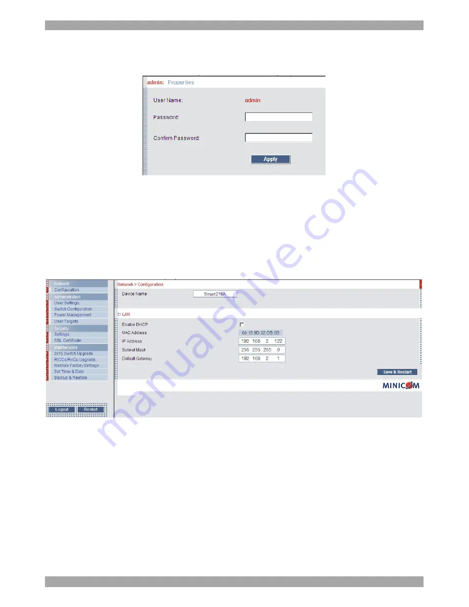
. The Network > Configuration appears, see 

Figure 14. 


Figure 14 Network > Configuration page 

11.1 Network > Configuration 

Consult your Network Administrator for the network settings. 


Device name - 

Type a name for the Smart 216.  

11.1.1 LAN 

In the LAN section – see Figure 14 – is the following: 

Enable DHCP

 – When a DHCP server is active on the same network to which 

Smart 216 is connected, DHCP provides automatic IP assignment. 

Summary of Contents for Minicom Smart 216

Page 1: ...972 2 535 9666 minicom minicom com North American HQ Linden NJ USA Tel 1 908 486 2100 info usa minicom com European HQ D bendorf Switzerland Tel 41 44 823 8000 info europe minicom com Technical suppor...

Page 2: ...ecting to the Local Area Network LAN 11 9 2 Setting network parameters via the OSD 11 9 2 1 Changing the Network parameters 12 10 Logging into the web configuration 13 10 1 Changing the password 14 11...

Page 3: ...ng a computer 26 22 3 Power management hotkey left Shift F12 27 22 4 Moving the Confirmation label F1 27 22 5 Tuning F5 28 22 6 The Settings window F2 28 22 7 DDC F10 29 22 8 Saving changes to the set...

Page 4: ...lation of the Canadian Department of Communications These above rules are designed to provide reasonable protection against such interference when operating the equipment in a commercial environment I...

Page 5: ...pendent of the operating system The Smart 216 is based on Minicom s innovative ROC technology in whereby computer server is directly connected to the switch via ROC dongles using only standard CAT5 ca...

Page 6: ...rver ports I 0 1 2 3 4 5 6 7 8 Keyboard Mouse Monitor USER 1 LAN Ethernet port LAN RPS Remote Power Switch RPS port 10 11 12 13 14 15 16 9 SERVER Keyboard Mouse Monitor USER 2 Figure 2 Smart 216 ports...

Page 7: ...l the equipment in an environment compatible with the maximum rated ambient temperature Reduced airflow Install the equipment in a rack in such a way that the amount of airflow required for safe opera...

Page 8: ...nit Front of unit Figure 3 Bracket positions Place the brackets towards the front of the unit so that the unit can be mounted front facing or place the brackets towards the rear of the unit so that th...

Page 9: ...The ROCs Each computer server is directly connected to the Smart 216 via the appropriate RoC using CAT5 cable in a star configuration No external power is needed at the ROCs The ROCs draw their power...

Page 10: ...ustrates the ROC PS 2 connections 3 Power on the server You can connect the ROC PS 2 to a powered on computer but it must be in the following order 1 Connect the Mouse connector to the computer s Mous...

Page 11: ...UN and SGI and all modern Linux distributions Figure 9 illustrates the ROC USB and its connections To connect the ROC USB 1 Connect the Screen connector to the computer s Video port 2 Connect the USB...

Page 12: ...ludes Assigning server names User and security settings Maintenance 9 1 Connecting to the Local Area Network LAN Configuration is done mainly via a web interface For this purpose connect a network cab...

Page 13: ...a or by pressing the spacebar whichever is relevant 9 2 1 Changing the Network parameters DHCP Enable When a DHCP server is active on the same network to which Smart 216 is connected DHCP provides aut...

Page 14: ...Enter The login page appears 3 Type the default Administrator user name admin and password access both lower case 4 Press Enter The web interface opens at the Targets page See Figure 12 Figure 12 Tar...

Page 15: ...m From the menu click Configuration The Network Configuration appears see Figure 14 Figure 14 Network Configuration page 11 1 Network Configuration Consult your Network Administrator for the network s...

Page 16: ...or These parameters can be configured locally from the OSD as explained on page 11 11 2 Administration User Settings From the menu click User Settings Figure 15 appears Figure 15 User Settings On this...

Page 17: ...g on the security level chosen the user name and password parameters are different See section 13 on page 20 2 Select the permission type from the Permission box 3 Click the user appears in the list o...

Page 18: ...accessing the system can identify the servers easily To do so 1 From the menu click Switch Configuration The Switch Configuration window appears see Figure 16 Figure 16 Switch Configuration 2 In the...

Page 19: ...6 Figure 17 Power Management 2 Select the number of sockets on the power management switch in the Number of Sockets drop down menu SRPS has 8 3 Click The appropriate number of Managed by Sockets and S...

Page 20: ...Targets The User Targets Configuration window appears see Figure 18 Figure 18 User Targets Configuration 2 Select a user from the User drop down menu 3 Check the servers the user can access according...

Page 21: ...2 options Standard security policy High security policy 6 characters or more 8 characters or more must include at least 1 digit and 1 upper case letter and 1 special character as follows _ Must not in...

Page 22: ...ord Click The certificate installs The device restarts automatically 15 Maintenance Switch Upgrade Upgrade the Smart 216 firmware to take advantage of new features Download the firmware from the Suppo...

Page 23: ...ers connected to the ROCs you wish to upgrade Click to select all 3 Verify the current version of the firmware by pressing 4 Locate and upload the firmware file 5 Press the firmware upgrades Figure 22...

Page 24: ...re 23 Restore factory settings 2 Check the box if you want to preserve Network settings 3 Click The unit restarts 18 Set Time Date The time and date set is used when recording log events see page 25 T...

Page 25: ...estore the configuration data browse to locate the file and click the device restarts 20 Saving changes and logging out To save any configuration changes click the relevant button on the current page...

Page 26: ...page Figure 26 Events log Navigate through the events pages using the forward or backward arrows marked as A in Figure 26 From the drop down menu marked as B in Figure 26 choose the number of events...

Page 27: ...s On Server status Off Figure 27 OSD Main window 22 1 Navigating the OSD Main window To navigate up and down use the Up and Down arrow keys To exit the OSD press Esc 22 2 Selecting a computer To selec...

Page 28: ...ys to navigate up and down and press Enter to select the power option 4 A prompt appear see Figure 29 Select the desired option and press Enter The power command is sent Figure 29 Power prompt 22 4 Mo...

Page 29: ...quality is relative to distance The further away a computer is from the Smart 216 the lower the image quality and the more tuning needed So place the higher resolution computers closer to the Switch 2...

Page 30: ...e DDC information of the monitor connected to the Smart 216 switch into the memories of all connected ROCs when first installing system To input the DDC information Press F10 Please wait flashes a few...

Page 31: ...the Smart 216 and RJ45 x 32 for the Smart 232 Weight 2 343Kg 5 165lbs Dimensions H x D x W 44 x 270 x 431 mm 1 7 x 10 6 x 17 Power input 100 240 VAC 0 8 A 50 60 Hz Operating temperature 0 C to 40 C 3...

Page 32: ...ppears on the front cover 26 WEEE compliance WEEE Information for Minicom Customers and Recyclers Under the Waste Electrical and Electronic Equipment WEEE Directive and implementing regulations when c...

Page 33: ...France Vincennes Tel 33 1 49 57 00 00 info france minicom com Italy Rome Tel 39 06 8209 7902 info italy minicom com England Tel 44 121 288 0608 info uk minicom com China Beijing Tel 86 21 6445 3181 In...

Page 34: ...SMART 216 232 33...

Reviews: