(
1
)
(
1
)
(
2
)
(
3
)
(
2
)
(
4
)
Structure and Assembly/Disassembly of the Machine
( 1)
( 1)
( 2)
( 2)
( 3)
( 4)
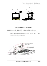
Figure 2-28 Disassembly of CRT screen filter
1.4.8Disassembly of the keyboard, trackball and buzzer
1. Remove the two keyboard silicone rubber caps, and then remove 2 M3×6
screws fixing the keyboard upper cover;
Figure 2-29 Remove the silicone rubber caps
DP-3300/DP-3200
Service Manual
(
V1.1
)
2-21
Summary of Contents for DP-3200
Page 1: ...DP 3300 DP 3200 Digital Ultrasonic Diagnostic Imaging System Service Manual...
Page 2: ......
Page 11: ...DP 3300 DP 3200 Service Manual V1 1 I...
Page 12: ......
Page 16: ......
Page 20: ......
Page 76: ......
Page 81: ...P N 2302 20 34499 V 1 1...


