background image


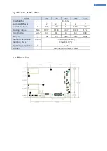
2.  Specifications of the Drive


2-1  Specifications 

Type of Drive 

CK10 Series 

Input Power(Control) 

24VDC ± 10% 

Input Power(Motor Drive) 

22VDC ~ 50VDC 

Control Method 

Closed loop control with ARM-based 32-bit MCU 

Multi Axes Drive 

Maximum 16 axes through Daisy-Chain 

Position Table 

128 motion command steps (Move, Wait, Loop, Jump, External control. 
etc) 

Current Consumption   

Max. 500mA ( Except motor current )   

O

per

at

ing


condi

ti

on 


Ambient   
Temperature   

Operating : 0~50


Storage : -20~70


Humidity   

In use : 35~85%RH (No condensation) 
In Storage : 10~90%RH (No condensation) 

Vib. Resist.   

0.5G 

F

u

n

ct

io

n


Rotation Speed   

0~3,000 [rpm] 

Resolution    [P/R] 

500 1,000 1,600 2,000 3,200 3,600 4,000 4,800 5,000 6,400 8,000 9,600 
10,000 16,000 20,000 (Available to set by the paramter) * 

Protection 
Function   

Over Current Error, Over Speed Error, Position Tracking Error, Over Load 
Error, Over Temperature Error, Over Regenerated Voltage Error, Motor 
Connect Error, Encoder Connect Error, In-Position Error, ROM Error, 
Position Overflow Error   

LED Display 

Power status, In-Position status, Enable status, Alarm status   

In-Position 
Selection   

0~63 (Selectable by parameter) 

Position Gain   
Selection   

0~63 (Selectable by parameter) 

Rotational 
Direction   

CW/CCW (Selectable by parameter) 

RUN Current   

50%~150% (Selectable by parameter)   
RUN current is flowing current value in the motor when motor is 
operating ( rotating ), It is set based on constant current of motor 

* Default factory setting value : 100%


STOP Current   

20%~100% (Selectable by parameter)   
It is set as setting value of STOP current 0.1 sec after motor stop. STOP 
current value is at a ratio against RUN current value of motor   

* Default factory setting value is : 50%
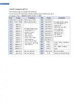
   

I/O 

Input Signals   

12 programmable inputs (Photocoupler)   

Output Signals   

10 programmable outputs (Photocoupler, Max. 30V 10mA)   

Drive Interface   

The RS-485 serial communication (Plus-R)   
- Communication speed: 9600, 19200, 38400, 57600, 115,200 [bps]   
Pulse I/F (Dir/Pulse, CW/CCW, A/B)   

Position Control   

Incremental mode / Absolute mode   
Data Range: -2,147,483,648 to +2,147,483,647 [pulse]   
Operating speed: Max. 3,000 [rpm]   

Return to Origin   

Origin Sensor, Z phase, ±Limit sensor, Torque   

GUI 

User Interface Program within Windows (Plus-R mode)   

Software   

Motion Library (DLL) for Windows XP/7/8/10 (Plus-R mode)   

* Up to the resolution of 16,000[ppr] the maximum speed can be reached by 3,000[rpm]. 
And if the resolution is over 16,000[ppr], the maximum speed will decrease accordingly.


Summary of Contents for CK10 Series

Page 1: ...1 DRIVER CK10 series User Manual VER 202108...

Page 2: ...8 I O connector CN3 12 4 Control I O signal 14 4 1 Input Signal 14 4 2 Output Signal 24 5 Operation 28 5 1 Servo ON Operation 28 5 2 Operation Mode 28 6 Other Operation Function 30 6 1 Position Table...

Page 3: ...sible for a product breakdown due to user s dismantling for the product and such a breakdown is not guaranteed by the warranty Safety Precaution 1 Before installation operation repairing the products...

Page 4: ...following the wiring diagram Otherwise a fire or malfunction of machine may occur Warning Before connecting cables check if input power is off Otherwise an electric shock or a fire may occur The case...

Page 5: ...d machine may get damaged Do not reconstruct the CK10 Otherwise an electric shock may occur or the product and machine get damaged And the reconstructed product cannot get after service 1 2 Note on In...

Page 6: ...table by parameter Position Gain Selection 0 63 Selectable by parameter Rotational Direction CW CCW Selectable by parameter RUN Current 50 150 Selectable by parameter RUN current is flowing current va...

Page 7: ...2 2 2 2 2 Current per Phase A 0 6 0 67 1 1 68 2 8 Holding Torque N m 0 037 0 118 0 137 0 431 1 72 Rotor Inertia g cm 2 3 3 18 14 68 480 Weights g 105 227 210 416 1075 Insulation Resistance Mohm 100 M...

Page 8: ...roller configuration 1 CK10 Connectors Switches No Function No Function CN1 Power EMG input SW1 ID Setting CN2 Motor SW2 RS 485 Termination CN4 Brake SW3 Setting S W CN5 Encoder J5 Communication port...

Page 9: ...9 3 2 External Wiring Diagram Note S GND is connected to GND in the drive...

Page 10: ...rrent Error The current through power devices in drive exceeds 4 8A 2 Over Speed Error Motor speed exceeds 3 000 rpm 3 Position Tracking Error Position error value is higher than 90 in motor run state...

Page 11: ...unction after power on can be programmable Please refer to the parameters settings 3 7 Power EMG input CN1 Motor power and control power are supplied separately and the rated current of driving motor...

Page 12: ...wer Ground B2 OUTPUT2 A3 INPUT1 Programmable input User Input 0 8 Limit Limit Org Sensor Org Search Jog Jog Stop Alarm Reset Servo On E Stop PT A0 A7 PT Start JPT IN0 2 B3 OUTPUT3 A4 INPUT2 B4 OUTPUT4...

Page 13: ...inductive loads Use free wheel diodes Select appropriate value of resistor R or load to meet specifications 3 Wiring CTL1 2 input When driving with the Open Collector circuit add external resistors so...

Page 14: ...sets the command position and the actual position to 0 in relation to motion position control The reset signal pulse scale is 10ms or more 3 User Input Signal The user input is connected to the IN pin...

Page 15: ...is not connected when motioning by PT Start signal the position table number will be 0 A7 A6 A5 A3 A2 A1 A0 PT NO 0 0 0 0 0 0 0 0 0 0 0 0 1 1 0 0 0 0 1 0 2 0 0 0 0 1 1 3 0 0 0 1 0 0 4 0 1 1 1 1 0 126...

Page 16: ...asserted when the PT A0 A6 signals are not assigned the PT No 0 will be executed 3 Checking the Moving and Inposition signals Between sequential PT Start command signal the checking step for motion st...

Page 17: ...ng input signal PT A0 A7 select corresponding PT number When Teaching signal is set to ON the position value pulse is saved to the position value of corresponding PT At this time it becomes the absolu...

Page 18: ...op signal is active in ON level and pulse scale is 10ms or more 8 Jog and Jog input When Jog or Jog signal is ON the motor rotates clockwise or counterclockwise until it reaches the hardware limit or...

Page 19: ...ion When Servo ON OFF signal is set to ON the drive restarts to supply the current to the motor and its torque is recovered Before operating the motor the user must set it to ON When the drive is set...

Page 20: ...Org Dir For more information refer to 1 2 Parameter When the origin search command is completed Origin Search OK signal is set to ON 11 E Stop Input When Emergency stop signal is set to ON the current...

Page 21: ...ignal conditions Example If PT 14 motion operates when there is no other input signal next m otion becomes PT 15 as shown in Figure 1 However if JPT Input0 Input2 input signal is set to ON while PT 14...

Page 22: ...n next motion is executed Example PT 14 Data PT No Wait Time JP Table No JPT 0 JPT 1 JPT 2 14 500 10015 10115 10116 10255 14 EMG Inputs Opening EMG inputs can force the drive to stop at emergency Once...

Page 23: ...motion Pause signal should be set to ON Case B When Pause signal is set to ON the motor starts to decelerate The signal is continuously maintained since the motor is completely stopped To start motion...

Page 24: ...and CK10_User Manual_Position Table 2 Inposition Output After the motor stop in target position exactly on Servo ON status the signal becomes ON The condition of this signal depends on parameter Posi...

Page 25: ...able When PT ACK signal is set to ON and PT End signal is set to OFF all motion loops are finished Then PT ACK signal becomes OFF and PT End signal becomes ON If the Wait time value in PT item is not...

Page 26: ...able Output 0 2 Output Control output used for Start Stop Message Function When these items are set this signal enables the user to check if corresponding PT motion starts or stops through control out...

Page 27: ...ck the motor during the servo off state CN4 is for brake connection Also control output port of CN3 can output brake signal This port needs addtional circuit to drive brake The function of setting the...

Page 28: ...command communication command DLL program or User Program GUI 1 Pulse Input Mode This controller can do motions by pulse input from the upper controller 1 Pulse Mode Pulse Dir inputs 2 Pulse Mode CCW...

Page 29: ...communication program Stopping Operation of Position Table When the motor is executing continuous operation of position table with CK10 stop executing position table by following methods To use DLL p...

Page 30: ...number to execute speed control operation For more information refer to User Manual Position Table Function Position Table Setting PT No Command type Position Low Speed High Speed Accel time Decel ti...

Page 31: ...ers according to inputting Jog and Jog signals Parameter Setting No Parameter Name Setting Value Unit 6 Jog Speed 1500 pps 7 Jog Start Speed 100 pps 8 Jog Acc Dec Time 200 msec Also when any value exc...

Page 32: ...rigin return is finished the motor moves additionally as this setting value and then stops 2 147 483 648 2 147 483 647 Org Position Set After origin return is finished Command Pos value is set to this...

Page 33: ...sor Dog is in the origin sensor In case of position of sensor Dog is between origin and Limit Sensor 2 Z Origin Org Method 1 In case of position of sensor Dog is between the origin and Limit Sensor In...

Page 34: ...r is 0 CW 4 Z Limit Origin Org Method 3 In case of Org Dir is 1 CCW case of Org Dir is 0 CW 5 Set Origin Org Method 4 It designates the current mechanical position as a origin irrespective of sensor 6...

Page 35: ...r In case of Org Dir is 1 CCW In case of Org Dir is 0 CW 8 Z Torque Origin Org Method 7 During the motion by Org Speed value It will stop motion when detects a force as much as Org Torque Ratio by con...

Page 36: ...on By using of control input or communication program command the user can do stop and emergency stop Even though the emergency stop command is inputted the Servo will be not OFF In case emergency sto...

Page 37: ...DLL program the user can check the trigger pulse output status Refer to CK10_UserManual_Communication Function_MODBUS The pulse is output only in bigger position area than pulse start position and is...

Page 38: ...After the work detected the motor will stop but the motor torque will be maintained and the inposition PT Stoped END signal is effective The maintained motor torque will be return to normal Servo ON s...

Page 39: ...s needed after Stop operation Extends the distance of Position motion command when Push motion is not excuted If the work can not be detect during Push Position the push mo de is Automatically finishe...

Page 40: ...8 2 147 483 647 Accel time Accel time of position motion 1 9 999 ms Deceleration time Decelerate time of position motion 1 9 999 ms Push ratio Motor torque value in push mode 20 90 Push motion Moving...

Page 41: ...r work detect Inposition signal is ON the Inposition signal change to OFF status But the PT Stopped END signal is still ON after the first work detect The push command is stopped at position 2 absolut...

Page 42: ...e PC by RS 485 serial communication PC s RS 232C port can be used By using following communication converters according to each communication type the user can connect the PC and the drive module The...

Page 43: ...through a mount hall of the PCB In this case use the STP CAT5E cable 7 2 Communication Interface Circuit It shows the input output circuit of RS 485 communication interface signal When the product is...

Page 44: ...Method 0 0 0 13 Reserved 14 Org Speed pps 1 500 000 5 000 15 Org Search Speed pps 1 50 000 1 000 16 Org Acc Dec Time msec 1 9 999 50 17 Org Method 0 7 0 18 Org Dir 0 1 1 19 Org Offset puls 2 147 483...

Page 45: ...limited by Pulse per resolution value In case of 10 000 500 000 In case of 16 000 800 000 pps 1 800 000 500 000 2 Axis Start Speed When position moving commands absolute move incremental move are giv...

Page 46: ...t stop motion by the limit sensor 0 stops the motor immediately by emergency stop mode 1 stops the motor gradually by soft stop mode 2 Do not use S W Limit 0 2 2 12 H W Limit Stop Method In case of st...

Page 47: ...the Z pulse origin return at the low value of Org Search Speed 6 The motor moves up to the wall by Org Torque Ratio and then immediately stops 7 The motor moves up to the wall by Org Torque Ratio and...

Page 48: ...ease the value until the motor s response is stabilized 3 Previously adjust the setting status by increasing decreasing one or two steps of the current setting value Va lue Integral Pa rt s Time Const...

Page 49: ...s greater than this setting value this mode generates an alarm to stop a flow of electricity to the motor and then set it to Servo OFF pulse 1 134 217 7 27 2 500 25 Motion Dir When the motor operates...

Page 50: ...of cannot set the acceleration time sufficiently it is applied to acceleration Example of use 1 28L Current 0 9 A 2 Run Current 10 100 3 Boost Current 1 50 4 Control current in case of acceleration 0...

Page 51: ...ng the communication speed The change of this parameter requires power off on cycle 0 9 600 1 19 200 2 38 400 3 57 600 4 115 200 0 4 4 38 Restore ActPos PT No CK10 stores current position and PT No to...

Page 52: ...Encoder Connect Error Cable connection error in Encoder connection of drive 10 In Position Error After operation is finished a position error occurs 12 ROM Error Error occurs in parameter storage dev...

Page 53: ...rating with load scale 2 Check assemble status of mechanism 3 Check SW limit value of parameter 4 Check the status of sensors 5 Check the motorDB for driver and motor Valid 5 Over Temperature Error 1...

Reviews: