background image

5

Using the Control Switch 

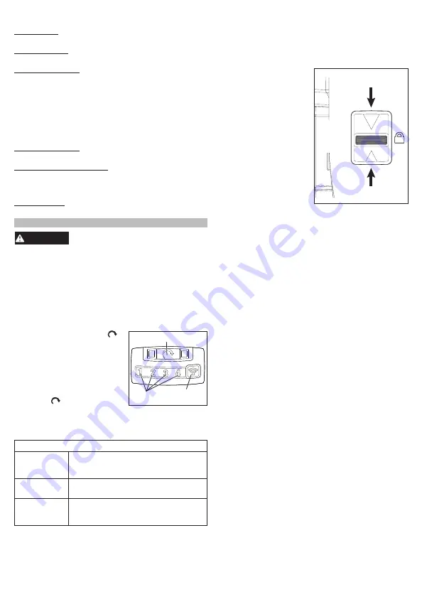
The control switch may be set to three positions: for

-

ward, reverse and lock. Due to a lockout mechanism, 

the control switch can only be adjusted when the trig

-

ger


is not pressed. Always allow the motor to come 

to a complete stop before using the control switch.

1. For 

forward 

(clockwise) 

Push for 

forward

Push for 

reverse

Push 

to 

center 

to lock

rotation, push the con-

trol switch in the direc-

tion shown. 

Check the 

direction of rotation 

before use.

2. For 

reverse

 (counter-

clockwise) rotation, 

push the control switch 

in the direction shown. 

Check the direction of 

rotation before use.

3. To 

lock

 the trigger, push 

the control switch to the 

center position. The trig

-

ger will not work when 

the control switch is in 

the locked position. 

  Always remove the battery pack before performing 

maintenance  or  changing  accessories. Always 

lock the trigger or remove the battery pack before 

storing the tool and any time the tool is not in use.

Starting, Stopping and Controlling Speed

These tools may be operated at any speed from 0 

to full speed. 

1. To 

start

 the tool, pull the trigger.


NOTE:

 An LED is turned on when the trigger is pulled.

2. To 

vary 

the driving speed, increase or decrease 

pressure on the trigger. The further the trigger is 

pulled, the greater the speed, up to the max RPM 

set by the MODE.

3. To 

stop

 the tool, release the trigger.

Impacting Techniques

The longer a bolt, screw, or nut is impacted, the 

tighter it will become. To help prevent damaging the 

fasteners or workpieces, avoid excessive impact-

ing. Be particularly careful when impacting smaller 

fasteners because they require less impacting to 

reach optimum torque.

Practice with various fasteners, noting the length of 

time required to reach the desired torque. Check the 

tightness with a hand-torque wrench. If the fasteners 

are too tight, reduce the impacting time. If they are 

not tight enough, increase the impacting time.

Oil, dirt, rust or other matter on the threads or under the 

head of the fastener affects the degree of tightness.

The torque required to loosen a fastener averages 

75% to 80% of the tightening torque, depending on 

the condition of the contacting surfaces.

On light gasket jobs, run each fastener down to a 

relatively light torque and use a hand torque wrench 

for final tightening.

MODE SETTINGS

Max Speed - Select the max RPM to be reached 

when running the tool in 

forward

Bolt Removal - Select the max RPM to be reached 

when running the tool in 

reverse

Precision Mode - Enable or disable, and set the 

limit on the torque output of the tool. For maximum 

torque  output,  set  the  Precision  Mode  to  OFF. To 

control the torque, set the Precision mode to ON 

and select the level. For lower torque applications 

select lower levels, and for higher torque applications, 

select higher levels. For torque-specific applications, 

confirm the final tightening torque with a calibrated 

torque wrench.

Trigger Ramp-Up - Set the length of time it takes for 

the tool to reach full speed.

Torque Level (Estimate)  (2869-20 only) - Review 

the torque range (350-450 ft-lbs). For precision ap

-

plications, confirm the final tightening torque with a 

calibrated device.

Star Patterns (2869-20 only) - Review the star pat-

terns for bolt installation/removal. 

OPERATION

WARNING

To reduce the risk of injury, always 

wear proper eye protection marked 

to comply with ANSI Z87.1.

When working in dusty situations, wear appro-

priate respiratory protection or use an OSHA 

compliant dust extraction solution.

Always  remove  battery  pack  before  changing 

or removing accessories. Only use accessories 

specifically recommended for this tool. Others 

may be hazardous.

Using the MODE Selector 

The mode selector button   is 

Mode Selector Button

Mode 

Indicators

ONE-KEY™

Indicator

used to select the mode set in 

the ONE-KEY™ app

To select the mode:

1. Pull and release the trigger 

to turn on the tool. The cur

-

rent mode indicator is lit.

2.  Press  the  mode  selector


button   to cycle through 

the  4  modes.  When  the 

desired mode indicator is lit, begin work.

3. The ONE-KEY™ Indicator lights, to indicate the 

following:

ONE-KEY™ Indicator

Solid Blue

Wireless mode is active and ready 

to be configured via the ONE-KEY™ 

app.

Blinking Blue Tool is actively communicating with 

the ONE-KEY™ app.

Blinking Red


Tool is in security lockout and can 

be unlocked by the owner via the 

ONE-KEY™ app.

Summary of Contents for M18 FUEL 2868-20

Page 1: ...KEY M18 FUEL OPERATOR S MANUAL MANUEL de L UTILISATEUR MANUAL del OPERADOR WARNING To reduce the risk of injury user must read and understand operator s manual AVERTISSEMENT Afin de r duire le risque...

Page 2: ...y Do not overreach Keep proper footing and balance at all times This enables better control of the power tool in unexpected situations Dress properly Do not wear loose clothing or jewelry Keep your ha...

Page 3: ...coin cell battery away from children WARNING To reduce the risk of injury when working in dusty situations wear appropriate respiratory protection or use an OSHA compliant dust extraction solution Alw...

Page 4: ...Ramp Up and review the Torque Level estimate and the Star Pattern for the mode The tool is shipped with the MODES preset as follows MODE 1 MODE 2 MODE 3 MODE 4 Control Type Custom Drive Custom Drive...

Page 5: ...er averages 75 to 80 of the tightening torque depending on the condition of the contacting surfaces On light gasket jobs run each fastener down to a relatively light torque and use a hand torque wrenc...

Page 6: ...ll battery keep it away from children and dispose of it properly 4 Insert the new coin cell battery 3V CR2032 with the positive side facing up 5 Close the battery door and tighten the screw s securely...

Page 7: ...PLY TO YOU THIS WARRANTY IS EXCLUSIVE AND IN LIEU OF ALL OTHER EXPRESS WARRANTIES WRITTEN OR ORAL TO THE EXTENT PERMITTED BY LAW MILWAUKEE DISCLAIMS ANY IMPLIED WARRANTIES INCLUDING WITHOUT LIMITATION...

Page 8: ...ue d affecter le bon fonctionnement de l outil En cas de dommages faire r parer l outil avant de l utiliser Plusieurs accidents sont caus s par des produits mal entretenus Garder les outils bien aff t...

Page 9: ...y figurent Si elles sont illisibles ou manquantes contacter un centre de services et d entretien MILWAUKEE pour un remplacement gratuit AVERTISSEMENT Certaines poussi res g n r es par les activit s d...

Page 10: ...hors du pivot d entra nement ONE KEY Pour de plus amples renseignements sur la fonc tion ONE KEY de cet outil veuillez visiter le site milwaukeetool com One Key Pour t l charger l application ONE KEY...

Page 11: ...NE KEY afficheront les car act ristiques suivantes Indicateur ONE KEY Bleu uni Le mode sans fil est engag et pr t pour le configurer l aide de l appli ONE KEY Bleu clignotant L outil tablit une commun...

Page 12: ...s et ouvrir la porte du compartiment de la pile bouton 3 Retirer la vieille pile bouton la tenir hors de la port e des enfants et se d barrasser d elle comme il faut 4 Mettre la nouvelle pile bouton 3...

Page 13: ...MAIS SANS S Y LIMITER TOUTE GARANTIE IMPLICITE DE QUALIT MARCHANDE OU D ADAPTATION UNE UTILISATION OU UNE FIN PARTICULI RE DANS LA MESURE O UNE TELLE STIPULATION D EXON RATION N EST PAS PERMISE PAR LA...

Page 14: ...rifique que no haya desalin eaci n amarre de partes m viles partes rotas o alguna otra condici n que pueda afectar el funcionamiento de la herramienta el ctrica Si se da a aseg rese de que la herramie...

Page 15: ...citaci n o informaci n adicional Conserve las etiquetas y las placas nominales Contieneninformaci nimportante Sisonilegiblesono est npresentes comun queseconuncentrodeservi cio MILWAUKEE para obtener...

Page 16: ...s y ac cesorios podr an fragmentarse o romperse y ocasionar lesiones C mo Colocar y Desmontar Accesorios 1 Utilice nicamente casquillos para v stagos de impulsi n cuadrados del tama o adecuado 2 Para...

Page 17: ...o calibrado solo modelo 2869 20 Patrones de estrella Revise los patrones de estrella para la instalaci n o remoci n de pernos solo el modelo 2869 20 OPERACION ADVERTENCIA Con el fin de minimizar el ri...

Page 18: ...el material como los sujetadores evite impactarlos en exceso Sea particularmente cuidadoso cuando impacte sujetadores que sean de tama o peque o ya que estos requerir n menos impactos para alcanzar el...

Page 19: ...pios secos y libres de aceite o grasa Use solo jab n neutro y un trapo h medo para limpiar ya que algunos substancias y solventes limpiadores son da inos a los pl sticos y partes aislantes Algunos de...

Page 20: ...ha de manufactura del producto se utilizar para determinar el periodo de garant a si no se proporciona comprobante de compra al solicitar el servicio en garant a LA ACEPTACI N DE LOS REMEDIOS EXCLUSIV...

Reviews: