background image

6

7

CAUTION

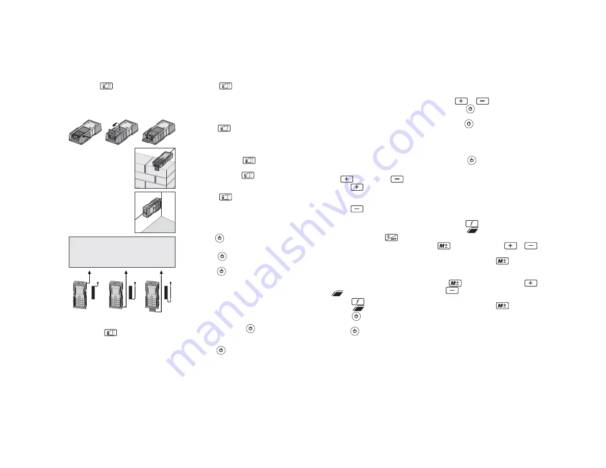
 Make sure that when 

measuring from the unfolded end 
bracket, the measuring reference 
is set to "End bracket" (C).

Press the 

2. 

 button two times to 

measure from the completely unfolded 
end bracket (C). After one measure-
ment, the reference returns automati-
cally to the default setting (B) (rear 
reference).
Press the 

3. 

 button three times to 

return to the rear reference setting.

To set and hold the measuring reference 
until the meter is turned off:

Press and hold the 

1. 

 button once 

to measure from the front edge (A).
Press and hold the 

2. 

 button again 

to measure from the completely un-
folded end bracket (C).
Press the 

3. 

 button return to the 

default setting, measuring from the 
rear of the meter (B).

Measuring 

Single Distance Measurement

Press the 

1. 

 button once to turn on 

the laser.
Press the 

2. 

 button again to make a 

distance measurement. 
The result is displayed in the Main Tar-

3. 

gets line. Previous measurements are 
displayed in the Intermediate Lines.

Continuous measurement with 
Minimum/Maximum-Measuring

Press and hold the 

1. 

 button. The 

meter will begin to beep and take 
measurements continuously.
Press the 

2. 


button again to stop the 

continuous measurements. 

The most recent measured value 

3. 

is displayed in the Main Targets 
line. The maximum and minimum 
measurements are displayed in the 
Intermediate Lines.

Use this function to determine the 
minimum or maximum distance from a 
specifi c measuring point (e.g. the deter-
mination of room diagonals (maximum 
value) or horizontal distance (minimum 
value)).

Functions

Addition 

 / Subtraction 


Press the 

1. 

 button once. The next 

measurement is added to the previous 
measurement.
Press the 

2. 

 button once. The next 

measurement is subtracted from the 
previous measurement.
Repeat this procedure as many times 

3. 

as required. Press the 

 button to 

cancel the last step.
The result is displayed in the Main 

4. 

Targets line, the most recent mea-
surement is displayed in Intermediate 
Line 1, the previous value is displayed 
in Intermediate Line 2.

Area 

Press the 

1. 

 button once to deter-

mine area 

.

Press the 

2. 

 button to take the fi rst 

measurement (e.g. length).
Press the 

3. 

 button again to take the 

second measurement (e.g. width).
The resulting area is displayed in the 

4. 

Main Targets line and the individual 
measurements are displayed in In-
termediate Line 1 and Intermediate 
Line 2.

A

B

C

Adding and subtracting areas

Determine the fi rst Area (see above)

1. 

Press 

2. 

 or 

.

Press the 

3. 

 button to take the fi rst 

measurement (e.g. length).
Press the 

4. 

 button again to take the 

second measurement (e.g. width).
The second area measurement is 

5. 

displayed, along with a fl ashing  "+" 
or "-". 
Press the 

6. 

 button to display the 

resulting added or subtracted area in 
the Main Targets line. The individual 
area measurements are displayed in 
Intermediate Line 1 and Intermediate 
Line 2.

Example of using stored measurements 
in a function

Press the 

1. 

 button once to deter-

mine area 

.

For the fi rst measurement, press the 

2. 

 button, then use the 

 or 


buttons to fi nd the desired value.
Press and hold the 

3. 

  button to 

enter the value into the function. 
For the second measurement, press 

4. 

the 

  button, then use the 


or 

 buttons to fi nd the desired 

value.
Press and hold the 

5. 

  button to 

enter the value into the function. 
The resulting area is displayed in the 

6. 

Main Targets line and the individual 
measurements from memory are 
displayed in Intermediate Line 1 and 
Intermediate Line 2.

To measure from an 
edge (B), fold out the 
end bracket until it snaps 
in for the fi rst time.

To measure out of a cor-
ner (C), fold out the end 
bracket, then continue 
to push it to the right 
and down until it opens 
completely. 

A

B

C

Reference 

The default reference setting is from 
the rear of the meter (A). An edge mea-
surement with a partially unfolded end 
bracket (B) will work in default mode.

To set the measuring reference for a 
single measurement:

P

1. ress 

the 

 button once to mea-

sure from the front edge (A). After one 
measurement, the reference returns 
automatically to the default setting (B) 
(rear reference). 

Summary of Contents for 2280-20

Page 1: ...MUST READ AND UNDERSTAND OPERATOR S MANUAL AFIN DE R DUIRE LE RISQUE DE BLESSURES L UTILISATEUR DOIT LIRE ET BIEN COMPRENDRE LE MANUEL DE L UTILISATEUR PARA REDUCIR EL RIESGO DE LESIONES EL USUARIO DE...

Page 2: ...in a cool dry place Do not store where temperatures may exceed 158 F 70 C such as in direct sunlight a vehicle or metal building during the summer Stay alert watch what you are do ing and use common s...

Page 3: ...2 3 4 5 6 6 OPERATION Timer Press the 1 button to set the timer to 5 seconds Use the or buttons to change the time lapse On the first measurement the count 2 down begins immediately For addi tional me...

Page 4: ...is displayed in Intermediate Line 1 the previous value is displayed in Intermediate Line 2 Area Press the 1 button once to deter mine area Press the 2 button to take the first measurement e g length P...

Page 5: ...sure a length using three points The distance to be measured flashes 2 on the display Press the button to take the measurement To determine the maximum distance press and hold the button A con tinuous...

Page 6: ...Display notices All display notices are either displayed with or Error The following errors can be corrected Electromagnetic Compatibility EMC The term electromagnetic compatibility is taken to mean...

Page 7: ...g contact your local distributor or a service center WARNING Always remove batteries before changing or remov ing accessories Only use accesso ries specifically recommended for this tool Others may be...

Page 8: ...re le polystyr ne et les autres surfaces semi perm ables semblables peuvent causer des er reurs de mesure Le fait de viser des surfaces luisantes peut faire d vier le faisceau laser et att nuer la pr...

Page 9: ...er les boutons ou pour modifier l intervalle 2 Au moment de la premi re prise mesure le d compte commence im m diatement Pour prendre d autres mesures appuyer sur le bouton afin de commencer le d comp...

Page 10: ...nir enfonc L appareil commence mettre un signal sonore et prendre des mesures de fa on continue 2 Appuyer de nouveau sur le bouton pour cesser de prendre des mesures de fa on continue 3 La plus r cent...

Page 11: ...ligne interm diaire 1 6 La valeur du volume s affiche sur la ligne Cibles principales La troisi me mesure s affiche sur la ligne interm diaire 1 et la deuxi me mesure s affiche sur la ligne interm dia...

Page 12: ...TISSEMENTL appareil de mesure de la distance au laser est conforme aux exigences les plus strictes des normes et des r glements applicables l heure actuelle on ne peut exclure compl tement la possibil...

Page 13: ...y compris l outil les blocs piles au lithium ion et le chargeur mais non les piles alcalines sont garantis l acheteur d origine tre exempt de vice du mat riau et de fabrication Sous r serve de certain...

Page 14: ...as bater as seg n los diagra mas de polaridad Deseche de inmediato las bater as usadas en forma correcta No incinere ni desarme las bater as En condiciones abusivas puede salir l quido expulsado de la...

Page 15: ...a 104 F ESPECIFICACIONES En condiciones dif ciles con luz solar intensa con una superficie objetivo poco reflectante o con temperaturas altas la desviaci n sobre distancias de aproxima damente 10 m 32...

Page 16: ...a vez para medir desde el borde delantero A Despu s de tomar una medici n la referencia vuelve autom ticamente a la configuraci n predeterminada B referencia posterior OPERATION Temporizador 1 Presion...

Page 17: ...2nd 1st Se obtienen mejores resultados cuan do se gira el tel metro sobre un punto fijo p ej el soporte de extremo est totalmente extendido y colocado contra una pared Use la funci n m nimo m ximo par...

Page 18: ...lanteo p ej 162 5 cm 64 para una distancia de replanteo de 406 4 mm 16 se muestra en la l nea intermedia 1 La distancia al siguiente punto de replanteo se mues tra en la l nea de objetivos principales...

Page 19: ...se produzca interferencia en una instalaci n concreta Si este equipo en efecto genera interferencia perjudicial para la recepci n de radio o televisi n que se puede determinar apagando y encendiendo...

Page 20: ...cinco 5 a os despu s de la fecha de compra Env e la herramienta de pruebas y mediciones y una copia del comprobante de la compra al centro de servicio m s cercano de f brica de MILWAUKEE Electric Too...

Page 21: ...te at www milwaukeetool com For service information use the Service Center Search icon found in the Parts Service section Additionally wehaveanationwidenetworkof authorizedDistributorsready to assist...

Reviews: