OM-261050 Page 59
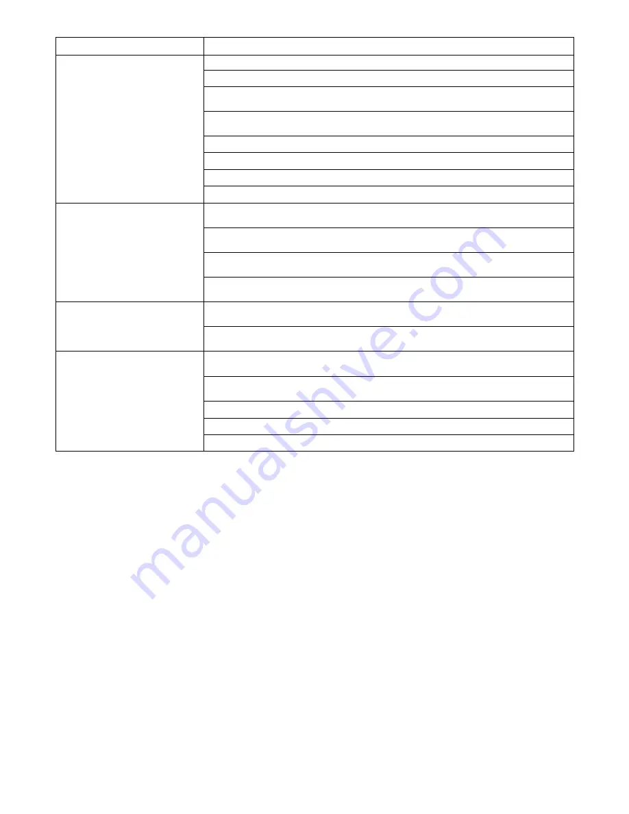
Trouble
Remedy
No outrigger operation.
No oil in system. Add oil.
Suction line valve closed. Open valve.
Hydraulic system not primed. Prime system (see Section 7-3). Check reservoir height meets require-
ments of Section 7-1.
Flow control valve H
−
FC1 not functioning. Check to make sure solenoid is plugged in. Check wiring
harness to solenoid coil. Have Factory Authorized Service Agent check solenoid coil integrity.
Flow control valve H
−
FC1 plugged with contaminants. Replace valve and flush system.
Belt to pump failed. Replace belt.
Tensioner for belt to pump failed. Replace tensioner.
Pulleys for pump failed. Replace pulleys and/or keys.
Slow outrigger operation.
Flow control valve H
−
FC1 is partially plugged with contaminates causing higher pressure drop across
the valve. Replace valve and flush system.
Differential pressure setting of pump (load sense) set too low. Have Factory Authorized Service Agent
check setting and correct as necessary.
Flow being dumped through crane relief valve instead of being directed to system, possibly caused by
system contamination. See crane manufacturer’s owners manual.
Hydraulic oil viscosity too high. Consult Section 7-1 for correct fluid viscosity recommendations at
specific ambient temperatures.
Fast outrigger operation.
Differential pressure setting of pump (load sense) set too high. Have Factory Authorized Service
Agent check setting and correct as necessary.
Hydraulic oil viscosity too low. Consult Section 7-1 for correct fluid viscosity recommendations at
specific ambient temperatures.
Crane lifting capacity not met (low
pressure).
Pump maximum pressure setting too low. Check setting and correct as necessary.
Check crane model hydraulic requirements. Pump may need to be reset (consult Factory Authorized
Service Agent).
Relief valve in crane system set too low. See crane owner’s manual to correct.
Relief valve in crane system stuck open from contamination. See crane owner’s manual to correct.
Hydraulic pump belt slipping. Replace belt and/or tensioner.
Summary of Contents for ENPAK
Page 47: ...OM 261050 Page 43 10 2 Remote Panel Use With Section 10 3 248 998 1 2 6 3 4 5 7 8 9 10 11...
Page 64: ...OM 261050 Page 60 SECTION 13 DIAGRAMS Figure 13 1 Training Circuit Diagram For EnPak...
Page 65: ...OM 261050 Page 61 261 040 D...
Page 66: ...OM 261050 Page 62 257 926 C Figure 13 2 EnPak Circuit Diagram...
Page 67: ...OM 261050 Page 63 261 045 A Figure 13 3 Air Compressor Diagram...
Page 79: ...OM 261050 Page 75 Notes...
Page 94: ...OM 261050 Page 90 Notes...


