8.2 Connector
assignments
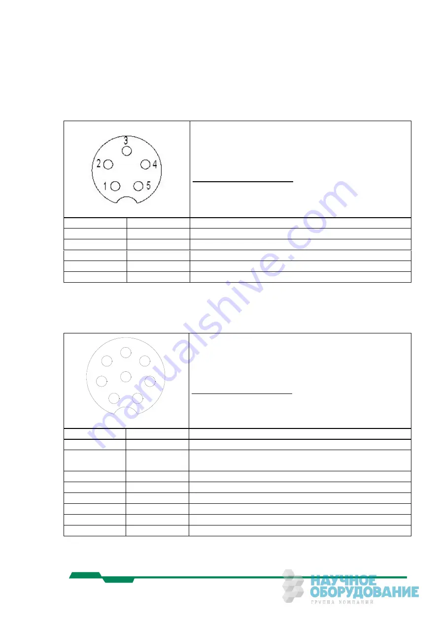
8.2.1 „Power“ connector, male, type Binder (Cube1/2/3)
connector (male), view: Solder side
180°; Binder # 99-0413-10-05 (shielded, recommend.)
90°: Binder # 99-0413-75-05 (shielded, recommend.)
www.binder-connector.de
Pin Nr.
Signal Level
Description
1 Power
+10,5..24V=
2 Power
+10,5..24V=
3 n.c.
4 Power
GND
5 Power
GND
Table 8.2-1
8.2.2 “Signal input / Sync” connector, male, type Binder (Cube1/2/3)
1
2
3
4
5
6
7
8
connector (male), view: Solder side
180°; Binder # 99-0425-10-08 (shielded, recommend.)
90°: Binder # 99-0425-75-08 (shielded, recommend.)
www.binder-connector.de
Pin Nr.
Signal Level
Description
1 GND
GND
2 0..2.5V@
1M
Ω
Analog input voltage, 8-Bit resolution
3
LVTTL
Sync Output / ARM
4
LVTTL
Digital Input 1
5
LVTTL
Digital Input 2
6
LVTTL
Digital Input 3
7
LVTTL
Digital Input 4/ Trigger Input
8 LVTTL
SYNC
Input
Table 8.2-2
MotionBLITZ Cube
User Manual Ver. 1.8.0
73
Summary of Contents for Cube5 C
Page 78: ...8 3 Spectral response 8 3 1 Cube1 Cube2 MotionBLITZ Cube User Manual Ver 1 8 0 78 ...
Page 79: ...8 3 2 Cube3 Cube5 MotionBLITZ Cube User Manual Ver 1 8 0 79 ...
Page 80: ...8 3 3 Cube4 MotionBLITZ Cube User Manual Ver 1 8 0 80 ...
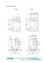
Page 85: ...8 5 4 Side view Cube4 5 c mount f mount MotionBLITZ Cube User Manual Ver 1 8 0 85 ...


