


Mighty Therm HH-PH Hydronic Boilers
Page 13
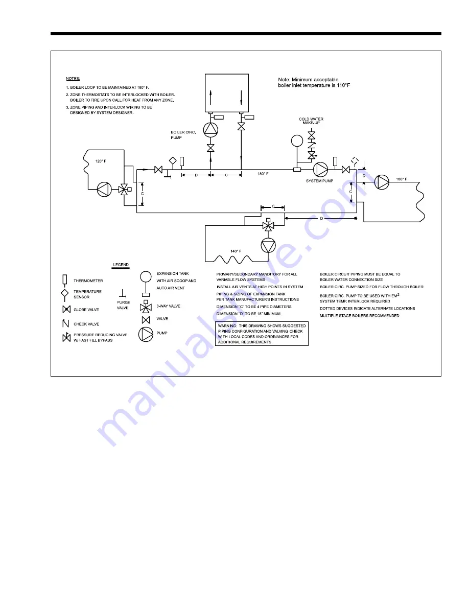
Figure 23. Hydronic Piping — One Boiler, Multi-Temperature System.
The correct flow rate can be verified by checking
the temperature rise of water as it passes through the
boiler. To check the temperature rise, measure the
difference in water temperature between the boiler
inlet and outlet to determine flow. For example: If a
Size 325 boiler is installed; the inlet water temperature
is 160°F (71°C); and the outlet water temperature is
185°F (85°C); then there is a 25°F (14°C) temperature
rise. Per Table 3 this equals a flow rate of 20 GPM
(1.3L/s) and a head loss (pressure drop) of 2.1 feet of
water. If a higher temperature rise is measured, flow
must be increased by changing the piping or pump
size.
2F-4. Variable Water Flow Systems
There can be reduced water flow through the
boiler in heating systems using zone valves, zone
pumps or 3-way valves. This can result in a high
temperature rise across the boiler. Laars recommends
primary-secondary pumping for all variable flow
systems. The boiler pump in a primary-secondary
system maintains constant flow through the boiler
even though the system flow is variable. In a primary-
secondary system the pressure drop of the boiler is not
added to the system (see Figures 21, 22 and 23).
2F-5. System Pressure Requirements
The HH-PH boilers are designed to operate on
closed, pressurized systems. A minimum of 12 psi
(82.7kPa) should be maintained on the system where
boiler supply water temperatures are 200°F (93°C) or
less. If higher temperatures are required, the minimum
system pressure should be at least 15 psi (103.4 kPa)
above the water vapor pressure corresponding to the
elevated water temperature.
Do not use the HH-PH boilers to operate on
open, pressurized systems unless the supply water
temperatures are kept below 180°F (82°C), and a
minimum of 5 psi (34.5 kPa) static head is maintained
at the boiler.


