


15
INITIAL OPERATION
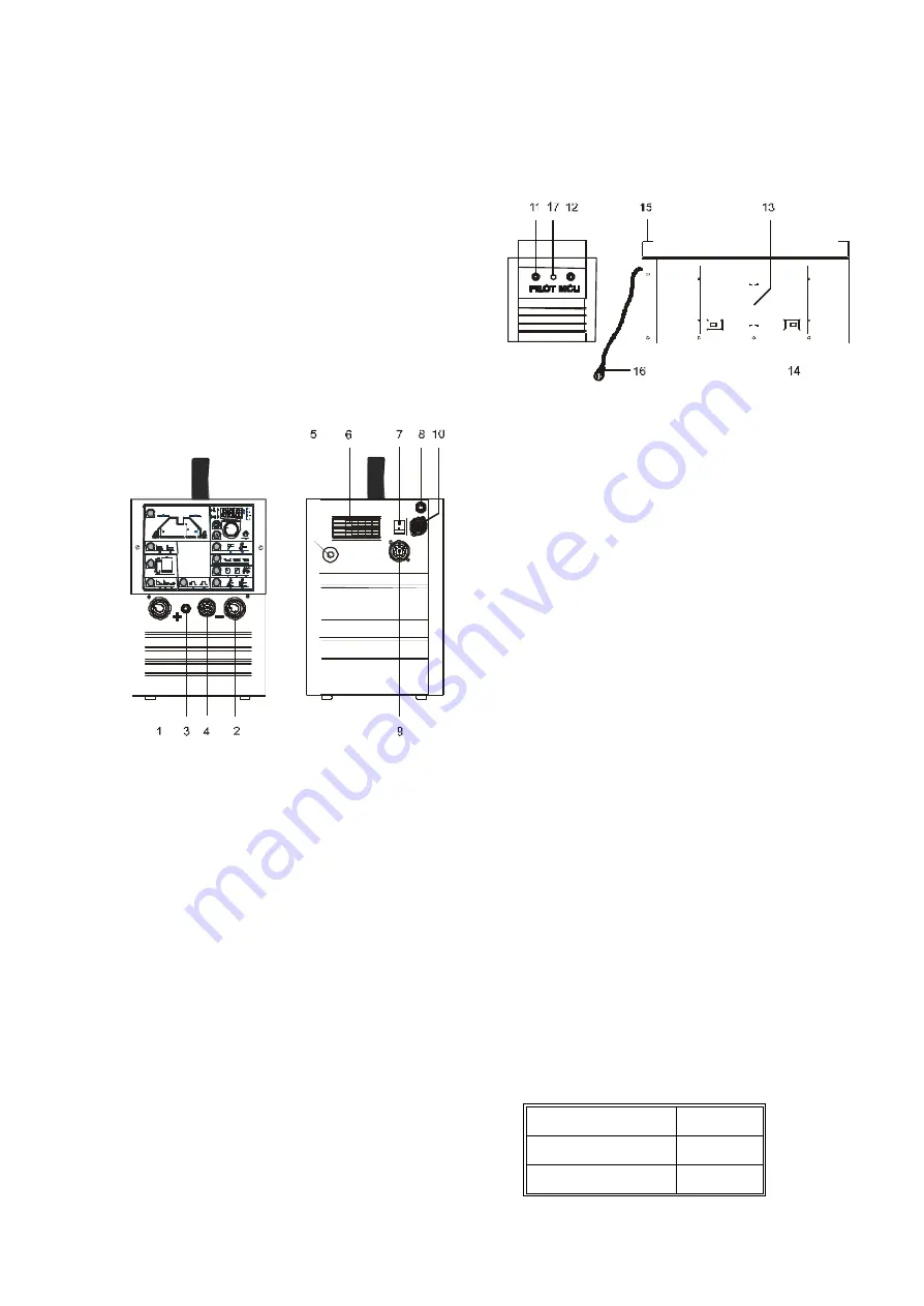
Mains connection
PILOT 1800/2400 must be connected to a mains
supply with 3 phases and protection earthing. After
the mains plug has been connected to the mains
cable (5) the machine is ready for use. Please note
that all cable connections must be made by
authorised and qualified staff. Switch on and off the
machine by means of the breaker (7) on the rear of
the machine.
Configuration
MIGATRONIC disclaims all responsibility for
damaged cables and other damages related to
welding with under sized welding torch and welding
cables measured by welding specifications e.g. in
relation to permissible load.
Gas connection
Connect the machine to the gas system by means
of a gas flow control. Press the gas hose mounted
with a quick connection on the gasconnection on the
rear of the machine (8).
Connection of welding cables
Connect the welding cables and the return current
cable to the front of the machine (1 and 2). Please
note that the plug must be turned 45 degrees after
insertion into the socket - otherwise the plug can be
damaged due to excessive contact resistance.
Connect always the TIG connection in the minus (-)
tap (2) and the return current cable in the plus (+) tap
(1).
The control signals from the TIG torch are trans-
formed to the machine through the circulary 7-poled
plug (4). When the plug has been assembled please
secure it by turning the "circulator" clockwise.
Connect the gas hose to the quick connection (3).
Electrodes are marked with a polarity on the pack-
ing. Mount the electrode tongs in accordance with
this marking to the plus/minus taps of the machine
(1 and 2).
Connection of external adjustment
Connect the remote control unit on the rear of the
machine on the circulary 8-poled plug (9).
Connection of a cooling module
Fastened the module under the machine with the
fitting (15). Mount the 4-poled plug (16) in the
corresponding socket in the machine (10). Mount the
flow hose on the water cooled torch in the quick
connection marked with blue (11) and the return
hose in the quick connection marked with red (12).
Control of cooling liquid and draining
The cooling liquid level can be inspected in the
inspection cover frame (13). Refillment of cooling
liquid should be carried out behind the cover (14). In
case of problems when starting up, the drain plug
(17) should be loosened.
Usage of the machine
(PILOT 2400)
When welding with PILOT 2400 machines a heating
of various components of the machine takes place
and during breaks these components will cool down
again.
It must be ensured that the air intake and outlet are
not blocked.
It is not possible to overload the machine in normal
use, and there is no need for cooling down periods at
current settings up to 160 Amps. When the machine
is set for welding currents higher than these, there
will be a need for periods during which the machine
can cool down.
The length of these periods depends on the current
setting, and the machine should not be switched off
in the meantime. If the periods for cooling down
during use of the machine are not sufficiently long,
the overheating protection will automatically stop the
welding process and the yellow LED will come on.
The yellow LED switches off when the machine has
cooled down sufficiently, and the machine is ready
for welding.
Max. load is:
100% max. load
160 A
60% max. load
200 A
35% max. load
240 A
Summary of Contents for PILOT 1800
Page 73: ...73 PILOT 1800 2400...
Page 74: ...74 WATER COOLING UNIT PILOT 1800 2400...
Page 76: ...76...
Page 82: ...82 PILOT 1800 2400 VANDK LEMODUL WATER COOLING UNIT WASSERMODUL MODULE HYDRAULIQUE...
Page 84: ...84...
Page 85: ......


