background image

GR8-1250 WalMaRT

Midtronics Inc.     7000 Monroe Street     Willowbrook, IL 60527

www.midtronics.com

7

5.  Charger location

5.1  Locate  the  charger  as  far  away  from  the  battery  as  the 

charger cables permit.

5.2  Never place the charger directly above the battery being 

charged; gases from the battery will corrode and damage 

the charger.

5.3  Never allow battery acid to drip on the charger when tak-

ing gravity readings or filling a battery.

5.4  Operate the charger only in a well-ventilated area that is 

free of dangerous vapors.

5.5  Store the charger in safe, dry location and maintain it in 

perfect condition.

5.6  Do not set the battery on top of the charger or where its 

acid might drip onto the charger.

6.   DC Connection Precautions

6.1  All switches should be set in the OFF position and AC cord 

should be DISCONNECTED from electrical outlet before you 

connect and disconnect the charger clamps. Never allow the 

clamps to touch each other.

6.2  When attaching the charger clamps, be certain to make 

the best possible mechanical as well as electrical connec-

tion. This will tend to prevent the clamps from slipping off 

the  connections,  avoid  dangerous  sparking,  and  assure 

safer and more efficient charging. The clamps should be 

kept clean. 

Hazardous voltage. 

Can cause death or serious 

personal injury.

Setting  the  switches  to “OFF”  does 

not  always  disconnect  the  charger 

electrical circuit from the AC power 

cord or the DC charger clamps.

7.   Connecting To The Battery

Risk of explosive gases

A spark near the battery may cause a battery 

explosion.  Follow these steps when the battery 

is installed in the vehicle to reduce the risk of 

explosion.

7.1  Before working on the vehicle, firmly apply the emergen-

cy  brake  and  place  the  gear  shift  to  NEUTRAL—shift  an 

automatic transmission to PARK.

7.2  Locate  the  charger  as  far  away  from  the  battery  as  the 

charger cords permit and position the AC and DC cords to 

avoid stepping on or tripping over them and to prevent 

damage by hood, doors, or moving engine parts.

7.3  Stay clear of fan blades, belts, pulleys, and any other parts 

that can cause physical injury.

7.4  Turn OFF all vehicle loads, including door lights, and cor-

rect any defects in the vehicle’s electrical system that may 

have caused low battery.

7.5  Check  the  polarity  of  the  battery  posts.  The  POSITIVE 

(POS.,  P,  +)  post  usually  has  a  larger  diameter  than  the 

NEGATIVE (NEG., N,–) post.

7.6  Determine which post of the battery is grounded (connect-

ed) to the chassis. If the negative post is grounded (as in most 

vehicles), see paragraph 7.7. If the positive post is grounded, 

see paragraph 7.8.

7.7  For a negative-grounded vehicle, first connect the  POSI-

TIVE  (RED)  clamp  from  the  charger  to  the  POSITIVE 

(POS., P, +) ungrounded post of the battery. Then connect 

the  NEGATIVE  (BLACK)  clamp  to  the  NEGATIVE  (NEG., 

N,–) post of the battery. Do not connect the clamp to the 

carburetor,  fuel  lines,  or  sheet-metal  body  parts.  When 

disconnecting the charger, turn all switches to OFF, dis-

connect the AC cord, remove the clamp from the NEGA-

TIVE battery terminal, and then remove the clamp from 

the POSITIVE battery terminal.

Safety Instructions

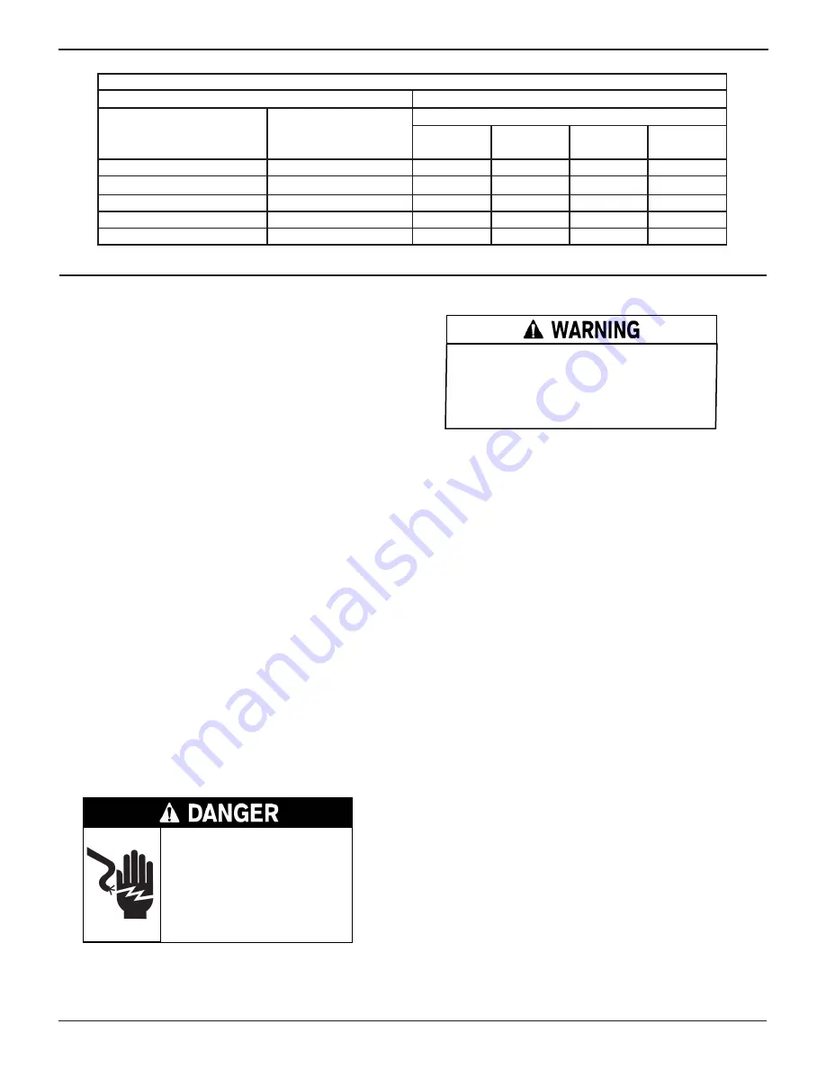
Table 1 - Recommended minimum AWG* size for extension cords for battery chargers

AC input rating amperes

AWG* size of cord

Equal or greater than:

But less than:

Length of cord, feet (m)

25

(7.6)

50

(15.2)

100

(30.5)

150

(45.6)

8

10

18

14

12

10

10

12

16

14

10

8

12

14

16

12

10

8

14

16

16

12

10

8

16

18

14

12

8

8

*American Wire Gauge

Summary of Contents for GR8-1250

Page 1: ...INSTRUCTION ManuAl GR8 1250 WALMART Multitasking Battery And Electrical Diagnostic Station June 2009 167 000155A...

Page 2: ...This page intentionally left blank...

Page 3: ...Chapter 3 Getting Started 18 Logging In for the First Time 18 Boot up 18 Selecting A Language 18 Zip Code 18 Setting User Preferences 18 Help Menu 18 Multitasking 18 Procedure Example 18 Chapter 4 Tes...

Page 4: ...eting A User ID 31 Editing A User ID 31 Info Upload 31 Display 31 Contrast Level 31 Coupon 31 Edit Coupon 32 Track Calls 32 Language 32 Admin 33 Options 33 Change Admin Pin 33 Clear Test Totals 33 Res...

Page 5: ...ire 1 7 To reduce risk of electric shock unplug the charger from the AC outlet before attempting any maintenance or cleaning Turning off the controls will not reduce this risk Remove marine boat batte...

Page 6: ...it matches the output rating of the battery charger 4 Grounding AC Power Cord Connections 4 1 The charger must be grounded to reduce risk of electric shock The charger is equipped with an electric cor...

Page 7: ...o reduce the risk of explosion 7 1 Before working on the vehicle firmly apply the emergen cy brake and place the gear shift to NEUTRAL shift an automatic transmission to PARK 7 2 Locate the charger as...

Page 8: ...y explosion Follow these steps when the battery is installed in the vehicle to reduce the risk of explosion WARNING Make sure all vehicle loads are OFF to prevent a possible arc 8 1 Check the polarity...

Page 9: ...a Never smoke or allow a spark or flame in the vicinity of a battery WARNING REQUIRED BY CALIFORNIA PROP 65 Bat tery posts terminals and related accessories contain lead and lead compounds chemicals k...

Page 10: ...ou register it online to activate your warranty Registration will also make it faster and easier for you to obtain technical support and service The serial number label is on the back of the Control M...

Page 11: ...the module down at an angle arrows until the bolts are inserted securely into the slots extend ing from the module s holes 4 Place the Charge Engine with the attached Control Mod ule on the cart 5 Co...

Page 12: ...g alarm to indicate transitions and warnings Serial Cable Connection Control Module The short serial cable connects the Control Module to the Multitask Bridge Multitask Bridge Allows the unit to charg...

Page 13: ...Serial Number On bottom of label required for product registration Multitask Bridge Charger Cable Connectors Serial Cable Connection Charge Engine Serial cable connection from Charge Engine to the Mu...

Page 14: ...e them as part of the keys ARROW keys Press the ARROW keys to scroll to numerical values and move to menus and icons POWER Key Press the POWER key to turn the control module ON and OFF Title Bar The t...

Page 15: ...cancels your choice or returns you to the previous screen although the word above it may also vary Examples BACK and CLEAR Menu Icons A menu icon is a graphical representation of a function you can se...

Page 16: ...ey represent while others are menu icons that lead to two or more options Menu Icon Description Tests a battery using the battery information you select in a series of screens Automatically tests char...

Page 17: ...en information on the GR8 using a data card Settings to adjust the screen contrast and backlight time Use this option to turn Coupon printing on or off Enables you to create a coupon at the bottom of...

Page 18: ...ons that you may want to re view prior to testing This menu also provides troubleshooting information and phone numbers for Midtronics Customer Service in case you encounter a problem and or need tech...

Page 19: ...a carry tool or strap to lift and transport the battery Failure to properly install lead terminal adapters or using adapters that are dirty or worn may cause false test results When testing side post...

Page 20: ...format MM YY for example 01 06 for January 2006 and press NEXT If the date code is unavailable press ENTER to continue IF AVAILABLE ENTER THE BATTERY DATE CODE MM YY Press the NEXT soft key to continu...

Page 21: ...ge reappears You may be testing too close to a noise source such as a charger or other high current device If so move away and retest If you are unable to find the source of the noise fully charge the...

Page 22: ...pacity During testing the GR8 accurately detects a battery s State of Charge and indicates this as part of the test results Table 4 Battery Decisions Battery Test Decision Recommended Action GOOD BATT...

Page 23: ...from the battery terminals 2 Connect the large clamps from the charge engine to the battery terminals 3 From the Main Menu highlight the DIAGNOSTIC icon and press the SELECT key 4 Use the UP or DOWN A...

Page 24: ...nt of current a battery can provide at 32 F 0 C 100 to 3000 8 Using the keypad or the UP and DOWN ARROW keys to select the BATTERY RATING CCA Press ENTER Charging Modes Diagnostic Charging has four mo...

Page 25: ...ternates between the CHARGING and TESTING screens The TESTING screens represent a two step process Step 1 The GR8 applies an electrical load and tests the bat tery s response Step 2 The GR8 measures t...

Page 26: ...capacity Selected rating Replaced AMP Hours Battery decision Maximum Charging Time Screen 2 of 3 Replace Range OK Replace Soon Range Good Range Screen 3 of 3 The GR8 displays one of three battery dec...

Page 27: ...or for all batteries tested using the New Battery Test Totals TOTALS counts the number of battery tests in two main categories TESTER TOTALS and CHARGER TOTALS Subcategories include LIFETIME USER TOTA...

Page 28: ...100 When the limit is reached you will no longer be able to test until you clear all results from memory Instructions follow on this page 3 Enter the information required in steps 5 through 8 in Chap...

Page 29: ...e your selection Time 1 Use the LEFT or RIGHT ARROW keys to highlight the hour minutes or AM or PM To rapidly scroll hold down an UP or DOWN ARROW key 9 19 PM 2 Press the SAVE soft key to save your se...

Page 30: ...AVE soft key to save your setting or the BACK soft key to return to the SHOP INFO screen without saving the changes Screen 2 5 YOUR COUNTRY 6 YOUR PHONE NUMBER 7 WWW WEBSITE COM 8 Screen 1 1 YOUR SHOP...

Page 31: ...into the Control Module the INFO UPLOAD utility updates Shop Coupon User and Screen information on the GR8 Display The LCD CONTRAST utility allows you to adjust the contrast of the text on the display...

Page 32: ...rather than move the file to your PC The default is OFF To set your preference 1 Use the UP or DOWN ARROW key or press the correspond ing numerical key 1 or 2 to move the dot to the option button of...

Page 33: ...ng to enable ON to display user defined text fields Default is off Change Admin Pin This function allows you to enter a new Admin Pin Clear Test Totals This function allows you to clear the test total...

Page 34: ...times as needed To add a space move the cursor forward by pressing the RIGHT ARROW key ENTER SCREEN TITLE Press the NEXT soft key to continue 4 Use the UP or DOWN ARROW key to move to the line you wan...

Page 35: ...de For charger this can only occur at main menu or in a charger test screen Tool will return to state that threw the error if the connection becomes valid For charger both the bridge and controller wi...

Page 36: ...les are connected Also make sure the Multitasker module is receiving power and is properly connected between the Control Module and the charger WIRELESS ERROR IS CHARGER TURNED ON ARE YOU WITHIN RANGE...

Page 37: ...d baking soda Periodically clean the clamps using a mixture of baking soda and water or a mild hand soap and a small bristle brush Clean the battery terminals If stud adapters are required fasten them...

Page 38: ...replace the equipment with a remanufactured equipment This limited warranty applies only to the specified equipment and does not cover any other equipment static damage water damage overvoltage damage...

Reviews: