MidNite Solar Classic Lite Quick Start Manual Download Page 8

Just the Facts for the Classic Lite (continued) 


8 | 

P a g e                                                                                                                       1 0 - 2 0 8 - 1         R E V :   A


LED Modes and Faults 

 
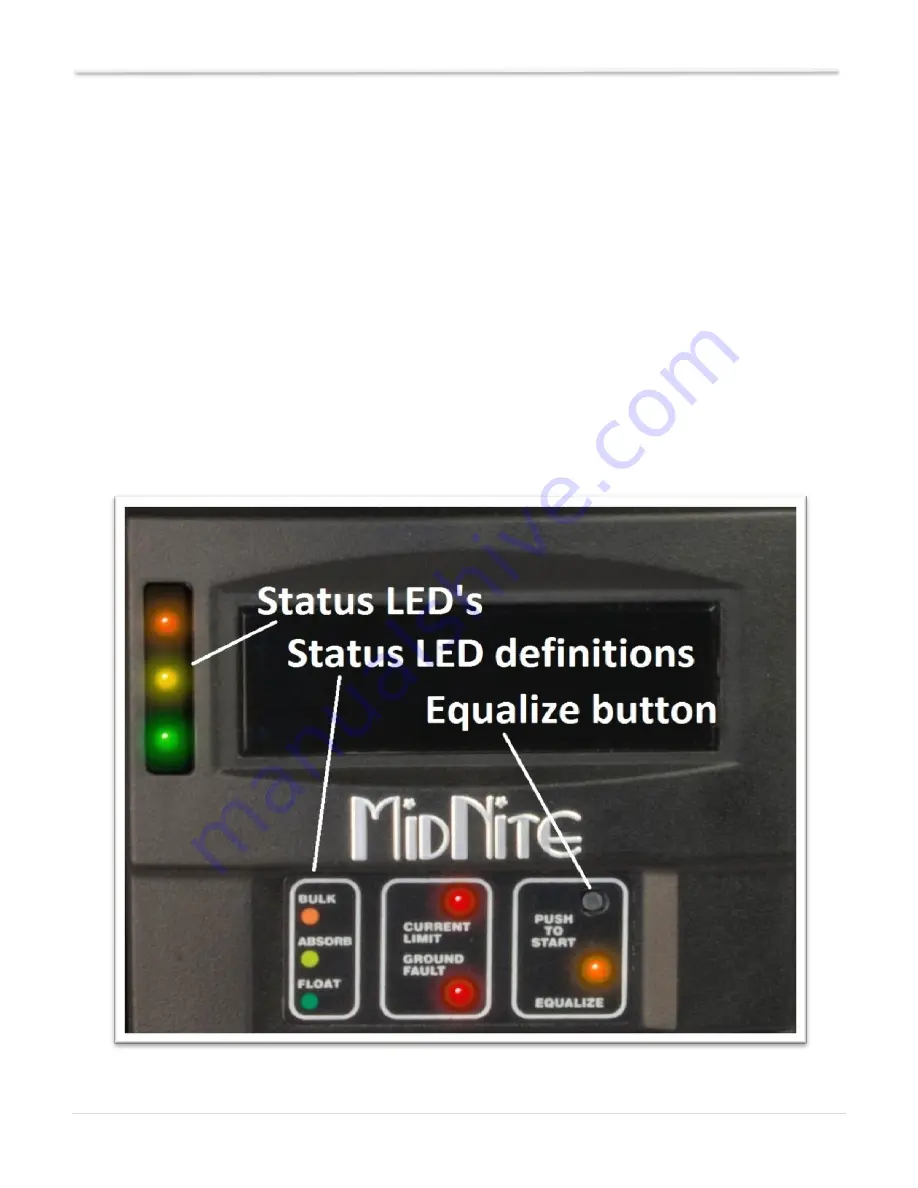
The Lite control panel (MNLP) has 6 status LEDs to indicate various modes of operation as well as faults. 
There are 3 behind the small window on the upper left.  
 
The top Orange status LED will light solid to indicate that the controller is in Bulk Charge mode.  
 
The center Yellow status LED will light solid to indicate that the controller is in the Absorption stage. 
 
The lower Green LED will light solid to indicate that the controller is in Float and blink slowly to indicate the 
controller is Resting due to low light. 

 
All 3 of these status LED’s will blink slowly to indicate “Wrong Code” please see the trouble shooting 
section for help with this. 
 
There are also LED indicators for Current limit, Ground Fault and Equalize. 
 
All LEDs blinking slowly indicate a loss of communication with the Classic. Check that the cable is 
plugged in to the top Jack on the Classic. If error persists try another cable or call Tech support for 
assistance. 


Figure 6


Summary of Contents for Classic Lite

Page 1: ...lease refer to the Classic Owner s Manual Included DVD or visit www midnitesolar com for all advanced features safety warnings and specifications Este manual tambi n est disponible en Espa ol La versi...

Page 2: ...is document and to periodically make changes to the content hereof without obligation or organization of such revisions or changes unless required to do so by prior arrangement Disclaimer Unless speci...

Page 3: ...to the Classic Lite 6 Wiring the Classic Lite 7 LED Modes and Faults 8 Dip Switches 9 Battery voltage and time settings 15 Using MNGP Remote to program a Classic Lite 16 Programming the Lite with a N...

Page 4: ...below if this is not the first time being opened The cable is not plugged in from the factory Unplug one end or the other and set the Front cover aside during wiring When replacing the cover be sure...

Page 5: ...r Router or wireless bridge USB cable for updating firmware and the Battery Temperature sensor On the blue terminal block from left to right Battery positive common negatives and DC input positive You...

Page 6: ...Fault Protection Dime not included Non Solar inputs to the Classic Lite The Lite will accept a wide variety of DC inputs from sources like Solar Wind Hydro Fuel Cells ETC One of the biggest concerns w...

Page 7: ...wiring diagram for installing the Classic on an E Panel Some installations may vary Please consult the Classic Owner s Manual for other diagrams There are 2 jumpers and a 4 position terminal strip Se...

Page 8: ...e controller is in the Absorption stage The lower Green LED will light solid to indicate that the controller is in Float and blink slowly to indicate the controller is Resting due to low light All 3 o...

Page 9: ...programmed using the standard Classic s MNGP 4 The Classic Lite can be programmed using the Local App Through the Ethernet connection software included on the DVD or available at www midnitesolar com...

Page 10: ...P as well as in Table 1 and Table 2 below Keep in mind if any of the switches are set to Custom the Lite display becomes a LED display only and you will need to use the included PC software or a MNGP...

Page 11: ...teries for KS model System Voltage Section 1 Switches 3 and 4 On Section 1 set Switches 3 and 4 to the appropriate positions shown in Table 1 corresponding to your system s battery voltage 12 24 and 4...

Page 12: ...Just the Facts for the Classic Lite continued 12 P a g e 1 0 2 0 8 1 R E V A The actual Labels that are on the inside of the MNLP Figure 9...

Page 13: ...Switch 3 Switch 4 12V Off Off 24V Off On 48V On Off Custom On On Battery Type Switch 5 Switch 6 Switch 7 Gel Off Off Off Sealed 1 Off Off On Sealed 2 Off On Off AGM Flooded Off On On Flooded 1 On Off...

Page 14: ...223 On Off Off 10 0 1 223 On Off On 10 0 1 224 On On Off 10 1 1 223 On On On MODBUS Port Switch 5 Switch 6 Switch 7 502 default Off Off Off 3900 Off Off On 3901 Off On Off 3902 Off On On 3903 On Off O...

Page 15: ...4 16 0 30 180 180 14 Custom 24 Volt battery Gel 28 27 4 30 90 Sealed 1 28 4 27 4 28 8 30 90 60 28 Sealed 2 28 6 27 4 29 2 30 90 60 28 AGM 28 8 27 4 30 2 30 120 120 28 Flooded 1 29 2 27 30 6 30 120 12...

Page 16: ...oper operation you will need to place the small black Jumper Figure 10 over both of the pins on the left most header as shown in Figure 11 below Do this to the Lite only The Lite can now be addressed...

Page 17: ...er Clearing Faults If either the Ground Fault or Current Limit fault light is lit then the equalize button can be tapped to clear these faults If the fault condition has not been removed however then...

Page 18: ...two purposes the first is to begin an Equalize stage the second is to clear faults Equalization An Equalize stage can be scheduled or started at any time by holding the Equalize button down for 2 3 s...

Page 19: ...There will be 4 more Jumpers just above the Blue DC Terminal block One of these can be used to replace the GFP jumper Contact Customer service for a replacement Jumper The Green Float Status LED blink...

Reviews: