


M thermal Mono
202008 69
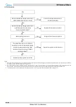
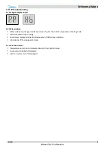
The specific error codes can also be obtained from the LED indicators LED1/LED2 on the inverter module.
Table 4-4.2: Errors indicated on LED for 18/22/26/30kW unit
LED1/2 flashing pattern
Corresponding error
Flashes 8 times and stops for 1 second, then repeats
L0 - Inverter module protection
Flashes 9 times and stops for 1 second, then repeats
L1 - DC bus low voltage protection
Flashes 10 times and stops for 1 second, then repeats
L2 - DC bus high voltage protection
Flashes 12 times and stops for 1 second, then repeats
L4 - MCE error(DC bus low or high voltage protection or software over current
protection)
Flashes 13 times and stops for 1 second, then repeats
L5 - Zero speed protection
Flashes 17 times and stops for 1 second, then repeats
L8 - Compressor frequency variation greater than 15Hz within one second protection
L9 - Actual compressor frequency differs from target frequency by more than 15Hz
protection
Flashes 3 times and stops for 1 second, then repeats
bH - Contactor stuck or 908 self checking fail
Flashes 5 times and stops for 1 second, then repeats
P1 - High pressure protection
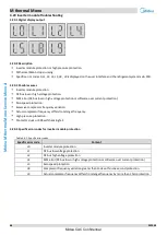
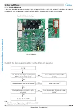
Figure 4-4.1: LED location of inveter module for three-phase 18/22/26/30kW unit
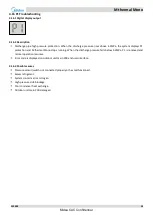
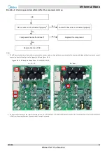
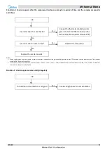
Principle of DC inverter
4.20.5
380-415V AC power supply change to DC power supply after bridge rectifier.
Contactor is open the current across the PTC to charge capacitor, after 5 seconds the contactor closed.
The capacitor output steady 540V DC power supply for inverter module P N terminals.
Power
supply
(380V AC)
A
B
C
Bridge
rectifier
PTC
Contactor
Inductor
Capacitor
Inverter module
(V
P-N
: 540V DC)
U
V
W
Compressor
P
N
3
1
2
Midea CAC Confidential


