


M thermal Mono
44
202008
M
id
ea
M
th
er
m
al
M
on
o
Se
rv
ic
e
M
an
ua
l
Procedure
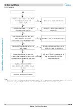
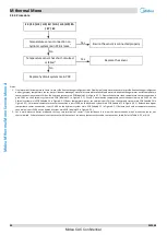
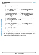
4.5.4
E3 / E4 / H2 / H3 / Ed / HA / H5 / H9/ Eb
/ E7 / EC
Temperature sensor connection on
hydronic system main PCB is loose
1
Yes
Ensure the sensor is connected properly
No
Temperature sensor has short-circuited
or failed
2
Yes
Replace the sensor
No
Replace hydronic system main PCB
Notes:
1.
Final water outlet temperature sensor,
water side heat exchanger refrigerant inlet (liquid pipe) temperature sensor, water side heat exchanger refrigerant
outlet (gas pipe) temperature sensor, water side heat exchanger water inlet temperature sensor and water side heat exchanger water outlet temperature
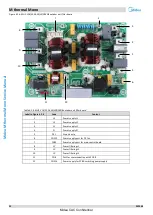
sensor connections are port CN6 on the hydronic system main PCB (labeled 10 in Figure 4-2.1).
Domestic hot water tank temperature sensor connection is
port CN13 on the hydronic system main PCB (labeled 13 in Figure 4-2.1). Circuit 2 water outlet temperature sensor connection is port CN15 on the
hydronic system main PCB (labeled 14 in Figure 4-2.1). Room temperature sensor connection is port CN11 on the hydronic system main PCB (labeled 24 in
Figure 4-2.1). Solar panel temperature sensor connection is port CN18 on the hydronic system main PCB (labeled 15 in Figure 4-2.1). Balance tank upper
temperature sensor connection is port CN24 on the hydronic system main PCB (labeled 11 in Figure 4-2.1) Balance tank nether temperature sensor
connection is port CN16 on the hydronic system main PCB (labeled 12 in Figure 4-2.1)
2. Set a multi-meter to buzzer mode and test any two terminals of sensor. If the resistance is too low, the buzzer sounds, which means the sensor has
short-circuited. If the resistance is not consistent with the sensor s resistance characteristics table, the sensor has failed. Refer to Table 4-5.1 or 4-5.3.
Midea CAC Confidential


