background image

14                                                                 

Specifications subject to change without notice.                                                                         32801002001

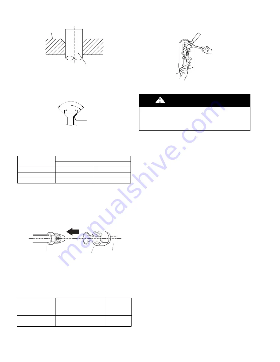
e. Clamp the flare block on the end of the pipe. The end of the 

pipe must extend beyond the flare form.

Fig. 43 — Flare Block

f.

Place the flaring tool onto the form.

g. Turn the handle of the flaring tool clockwise until the pipe is fully 

flared. Flare the pipe in accordance with the dimensions in Table 8 

on page 14.

Fig. 44 —Flare Shape

h. Remove the flaring tool and flare block, then inspect the end of 

the pipe for cracks and even flaring.

Table 8 — Flare Nut Spacing

6. Connect the Pipes

Connect the copper pipes to the outdoor unit first, then connect 
the pipes to the indoor unit. Connect the low-pressure pipe first, 
then connect the high pressure pipe.

1. When connecting the flare nuts, apply a thin coat of refrigeration oil

to the flared ends of the pipes.

2. Align the center of the two pipes that you will connect.

Fig. 45 — Align the center of the two pipes

3. Tighten the flare nut as much as possible by hand.
4. Using a wrench, grip the nut on the unit tubing.
5. While firmly gripping the nut, use a torque wrench to tighten the 

flare nut according to the torque values listed in Table 9.

Table 9 — Tightening Torque

NOTE: Use both a backup wrench and a torque wrench when 
connecting or disconnecting pipes to or from the unit.

Fig. 46 — Torque wrench with backup wrench

All tubing bends should be performed with a properly sized tubing 

bender to prevent kinking or damaging the tubing.

6. After connecting the copper pipes to the outdoor unit, wrap the 

power cable, signal cable and the piping together with binding tape.

NOTE: While bundling these items together, DO NOT intertwine 
or cross the signal cable with any other wiring.

7. Thread this lineset through the wall to connect to the indoor unit.

8. The liquid line sweat connection is 3/8” O.D. copper and the 

suction line sweat connection is 5/8” O.D. copper. Use the 

appropriate adapters for tubing that runs from the outdoor unit. Cut 

and deburr the tubing (review “Remove Burrs” on page 13) to 

prepare it for brazing. Setup the nitrogen apparatus and connect to 

the outside unit to flow nitrogen while brazing. Braze the tubing 

and any fittings to obtain a proper seal.

9. Adjust the nitrogen apparatus to pressurize the system. Pressure test 

the system to a maximum of 500 psig for at least 60 minutes.

10. Insulate both lines of the line set separately and completely, 

including the outdoor unit valves. 

OUTER DIAM. (MM)

A IN (MM)

MAX.

MIN.

Ø 3/8”(9.52)

0.06”(1.6)

0.04”(1.0)

Ø 1/2”(12.7)

0.07”(1.8)

0.04”(1.0)

Ø 5/8”(15.88)

0.09”(2.2)

0.08”(2.0)

BRASS FLARE SIZE

RECOMMENDED SEATING 

TORQUE FOR BRASS 

FLARE NUTS

N-M

Ø3/8

15-18 Ft. - Lbs

20.3 to 24.4

Ø1/2

28-32 Ft. - Lbs

38.0 to 43.4

Ø5/8

38-42 Ft. - Lbs

51.5 to 56.9

Flare block

Pipe

R0.4~0.8

45

qr

2

90

q

r

4

A

Pipe

Indoor unit tubing

Flare nut

Wrap insulation around the piping. Direct contact with the bare 
piping may result in burns or frostbite. Ensure the pipe is properly 
connected. Over tightening may damage the bell mouth and under 
tightening may lead to leakage.

CAUTION

Summary of Contents for DLFLAA

Page 1: ...work gloves Have a fire extinguisher available Read these instructions thoroughly and follow all warnings or cautions included in the literature and attached to the unit Consult local building codes a...

Page 2: ...allation parts and accessories to install the system Improper installation may result in water leakage electrical shock and fire or cause the equipment to fail Keep the installation manual in a safe p...

Page 3: ...84 11 8 299 13 3 339 3 0 75 2 5 64 4 9 124 6 8 174 1 7 44 A HEIGHT 48 1 1222 C WIDTH 19 7 501 4 8 121 2 4 61 6 7 171 2 2 57 D DUCT 18 2 462 E DUCT 10 3 262 B DEPTH 21 1 535 0 8 21 0 5 13 0 6 16 18 4...

Page 4: ...med according to the installation instructions Improper installation can cause water leakage electrical shock or fire In North America installation must be performed in accordance with the requirement...

Page 5: ...t is installed over a finished ceiling and or living area building codes may require a field supplied secondary condensate pan to be installed under the entire unit Some localities may allow as an alt...

Page 6: ...t 5 Install the drain lines Fig 7 Vertical Upflow Installations Fig 8 Horizontal Right Installations NOTE For a horizontal right installation secondary condensate pan field supplied must be installed...

Page 7: ...d drain pan assembly 9 Reinstall the pipe temperature sensor in its original position Attach the room temperature sensor to the evaporator output pipe protection sleeve Fig 15 Reinstall the Pipe Tempe...

Page 8: ...uipped with the electric auxiliary heat module please check the electric auxiliary heat module specification that is compatible with the unit to avoid unnecessary consequences caused by improper match...

Page 9: ...into the opening made by removal of the sheet metal cover s Ensure the two support rod ends are on the opposite bulkhead Fig 24 Insert Heating Module 5 Use the 3 screws 6 screws for 15K or 20K remove...

Page 10: ...quirements and local codes see Table 6 on page 11 Choose the power cord and the power cord installation location see Figure 30 Each circuit breaker group needs to connect to the power input line Where...

Page 11: ...do not have a 90 degree elbow and 10ft 3m of main duct to first branch takeoff may require internal acoustical insulation lining As an alternative fibrous ductwork may be used if constructed and insta...

Page 12: ...ood 2 Use a 2 5in 65mm core drill to drill a hole in the wall Make sure the hole is drilled at a slight downward angle so that the outdoor end of the hole is lower than the indoor end by about 0 5in 1...

Page 13: ...g an airtight seal a After removing the burrs from the cut pipe seal the ends with PVC tape to prevent foreign materials from entering the pipe b Sheath the pipe with insulating material c Place flare...

Page 14: ...nder to prevent kinking or damaging the tubing 6 After connecting the copper pipes to the outdoor unit wrap the power cable signal cable and the piping together with binding tape NOTE While bundling t...

Page 15: ...ost positive way of assuring a system is free of air and moisture see Fig 49 NOTE DO NOT add a filter line drier Fig 49 Deep Vacuum Graph Triple Evacuation Method The triple evacuation method should b...

Page 16: ...it would lose power A disconnect switch is not required on the indoor unit side on the wiring between the outdoor and indoor unit A 3 pole disconnect purchased separately may be used for extra protect...

Page 17: ...e is a ground wire To minimize voltage drop the factory recommended wire size is 14 2 power stranded with a ground Communication Wiring A separate 2 wire cable stranded shielded copper conductor with...

Page 18: ...0 5 0 20 120 36 5 0 42 250 48 5 0 65 400 3 S 1 L1 2 L2 208 230 1 60 Power Supply Main 1 L1 208 230 1 60 2 L2 3 S 1 L1 2 L2 CONNECTING CABLE OUTDOOR TO INDOOR Indoor Unit Power Supply 208 230 1 60 Indo...

Page 19: ...Indoor Unit Control Box Sizes 36 48 LED Display The control displays active faults codes on the LED display When the control displays the fault code and the LED flashes quickly there is something wro...

Page 20: ...nnected b Turn off the power to the indoor and outdoor units for 3 minutes c Turn the power back on Wait 1 minute and check the 24 volt Interface digital display If the display reads 00 then proceed I...

Page 21: ...troller exits the MODIFICATION mode After you power OFF the unit power the unit ON again and the unit retains the setting value Fig 65 RG57 Remote Controller FP Activate Disable freeze protection func...

Page 22: ...1 400 1 310 1 215 1 105 950 825 Low 1 525 1 450 1 372 1 280 1 190 1 074 935 785 650 36 SP1 High 1 335 1 270 1 165 1 062 950 810 645 450 240 Medium 1 185 1 100 990 845 685 520 335 Low 1 020 915 775 60...

Page 23: ...Pressurein WC High Medium Low SP4 0 200 400 600 800 1 000 1 200 1 400 1 600 1 800 2 000 0 0 0 1 0 2 0 3 0 4 0 5 0 6 0 7 0 8 Air ow CFM Sta cPressurein WC High Medium Low SP1 0 200 400 600 800 1 000 1...

Page 24: ...M Sta cPressurein WC High Medium Low SP2 0 200 400 600 800 1 000 1 200 1 400 1 600 1 800 2 000 0 0 0 1 0 2 0 3 0 4 0 5 0 6 0 7 0 8 Air ow CFM Sta c Pressurein WC High Medium Low SP3 0 200 400 600 800...

Page 25: ...conditioner Turn off the main power switch and reinstall the test cover NOTE If the unit malfunctions or does not operate according to your expectations please refer to the Troubleshooting section of...

Page 26: ...FF E0 Indoor unit EEPROM parameter error 2 times OFF E1 Indoor outdoor unit communication error 4 times OFF E3 The indoor fan speed is operating outside of the normal range 5 times OFF E4 Indoor room...

Reviews: