background image

32801002001                                                                            Specifications subject to change without notice.                                                                                         

11

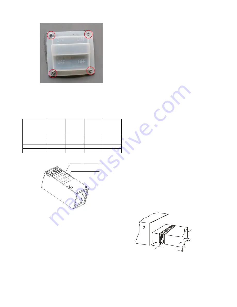
14. Fasten the resilient cap and seal on the upper cover plate with 4

screws.

Fig. 34 — Fasten the resilient cap

15. Reassemble the electronic control cover and secure it with screws. 

Reassemble the upper cover plate and secure it with screws. After 

the electric heating wiring is connected, confirm the plate is secure 

before powering the unit on. Check all the wiring and ensure a 

reliable connection with the wire body. 

Table 6 — Specifications

Fig. 35 — Indoor Unit Wiring Diagram

NOTE: 

The electric auxiliary heat wiring diagram is supplied with the 

accessories. Please paste the wiring diagram in the designated position 
after installing the heat modules.

Step 4 - Installing Ductwork

Connect the supply-air duct over the outside of the 3/4in (19 mm) 
flanges provided on the supply-air opening. Secure the duct to the 
flange, using proper fasteners for the type of duct used, and seal duct-
to-unit joint. If the return-air flanges are required, install the factory-
authorized accessory kit.
Use flexible connectors between the ductwork and unit to prevent 
transmission of vibration. When the electric heater is installed, use 
heat-resistant material for the flexible connector between the 
ductwork and the unit at the discharge connection. Ductwork passing 
through the unconditioned space must be insulated and covered with a 
vapor barrier.
Units equipped with 20kW electric heaters require a 1in (25mm) 
clearance to combustible materials for the first 36in (914mm) of 
supply duct.

DUCTWORK ACOUSTICAL TREATMENT

Metal duct systems that do not have a 90 degree elbow and 10ft (3m) of 
main duct to first branch takeoff may require internal acoustical insulation 
lining. As an alternative, fibrous ductwork may be used if constructed and 
installed in accordance with the latest edition of the SMACNA 
construction standard on fibrous glass ducts. Both acoustical lining and 
fibrous ductwork shall comply with the National Fire Protection 
Association as tested by UL Standard 181 for Class 1 air ducts.
The air supply and return may be handled in one of several ways; 
whichever situation is best suited for the installation (See Fig. 5 — on 
page 5). 
A large number of issues encountered with split-system 
installations can be linked to improperly designed or installed duct 
systems. It is therefore very important that the duct system be properly 
designed and installed.
Use of flexible duct collars is recommended to minimize the transmission 
of vibration/noise into the conditioned space. Where the return air duct is 
short, or where sound is liable to be a problem, sound absorbing glass fiber 
should be used inside the duct.
Insulation of duct work must be installed according to local codes and
best practices. The supply air duct should be properly sized by use of a
transition to match unit opening. 
This unit is not designed for non-ducted (freeblow) applications. Duct 
work should be fabricated and installed in accordance with local and/
or national codes.

Fig. 36 — Flexible Duct Collar Connection

Specifications

No. of 

Circuit 

Breakers

No. of 

Relays

No. of 

Power 

Cord 

Groups

No. of 

Power 

Cord 

Grounding 

Screws

5kW

1

1

1

1

10kW

1

2

1

1

15kW

2

3

2

2

20kW

2

4

2

2

Indoor unit wiring diagram

Electric auxiliary 
heat wiring diagram

Plenum Clearances

MINIMUM CLEARANCE
OF 1ft (25.4mm) ALL SIDES

RECOMMENDED FLEXIBLE
DUCT COLLAR

3.2ft (1m)

Summary of Contents for DLFLAA

Page 1: ...work gloves Have a fire extinguisher available Read these instructions thoroughly and follow all warnings or cautions included in the literature and attached to the unit Consult local building codes a...

Page 2: ...allation parts and accessories to install the system Improper installation may result in water leakage electrical shock and fire or cause the equipment to fail Keep the installation manual in a safe p...

Page 3: ...84 11 8 299 13 3 339 3 0 75 2 5 64 4 9 124 6 8 174 1 7 44 A HEIGHT 48 1 1222 C WIDTH 19 7 501 4 8 121 2 4 61 6 7 171 2 2 57 D DUCT 18 2 462 E DUCT 10 3 262 B DEPTH 21 1 535 0 8 21 0 5 13 0 6 16 18 4...

Page 4: ...med according to the installation instructions Improper installation can cause water leakage electrical shock or fire In North America installation must be performed in accordance with the requirement...

Page 5: ...t is installed over a finished ceiling and or living area building codes may require a field supplied secondary condensate pan to be installed under the entire unit Some localities may allow as an alt...

Page 6: ...t 5 Install the drain lines Fig 7 Vertical Upflow Installations Fig 8 Horizontal Right Installations NOTE For a horizontal right installation secondary condensate pan field supplied must be installed...

Page 7: ...d drain pan assembly 9 Reinstall the pipe temperature sensor in its original position Attach the room temperature sensor to the evaporator output pipe protection sleeve Fig 15 Reinstall the Pipe Tempe...

Page 8: ...uipped with the electric auxiliary heat module please check the electric auxiliary heat module specification that is compatible with the unit to avoid unnecessary consequences caused by improper match...

Page 9: ...into the opening made by removal of the sheet metal cover s Ensure the two support rod ends are on the opposite bulkhead Fig 24 Insert Heating Module 5 Use the 3 screws 6 screws for 15K or 20K remove...

Page 10: ...quirements and local codes see Table 6 on page 11 Choose the power cord and the power cord installation location see Figure 30 Each circuit breaker group needs to connect to the power input line Where...

Page 11: ...do not have a 90 degree elbow and 10ft 3m of main duct to first branch takeoff may require internal acoustical insulation lining As an alternative fibrous ductwork may be used if constructed and insta...

Page 12: ...ood 2 Use a 2 5in 65mm core drill to drill a hole in the wall Make sure the hole is drilled at a slight downward angle so that the outdoor end of the hole is lower than the indoor end by about 0 5in 1...

Page 13: ...g an airtight seal a After removing the burrs from the cut pipe seal the ends with PVC tape to prevent foreign materials from entering the pipe b Sheath the pipe with insulating material c Place flare...

Page 14: ...nder to prevent kinking or damaging the tubing 6 After connecting the copper pipes to the outdoor unit wrap the power cable signal cable and the piping together with binding tape NOTE While bundling t...

Page 15: ...ost positive way of assuring a system is free of air and moisture see Fig 49 NOTE DO NOT add a filter line drier Fig 49 Deep Vacuum Graph Triple Evacuation Method The triple evacuation method should b...

Page 16: ...it would lose power A disconnect switch is not required on the indoor unit side on the wiring between the outdoor and indoor unit A 3 pole disconnect purchased separately may be used for extra protect...

Page 17: ...e is a ground wire To minimize voltage drop the factory recommended wire size is 14 2 power stranded with a ground Communication Wiring A separate 2 wire cable stranded shielded copper conductor with...

Page 18: ...0 5 0 20 120 36 5 0 42 250 48 5 0 65 400 3 S 1 L1 2 L2 208 230 1 60 Power Supply Main 1 L1 208 230 1 60 2 L2 3 S 1 L1 2 L2 CONNECTING CABLE OUTDOOR TO INDOOR Indoor Unit Power Supply 208 230 1 60 Indo...

Page 19: ...Indoor Unit Control Box Sizes 36 48 LED Display The control displays active faults codes on the LED display When the control displays the fault code and the LED flashes quickly there is something wro...

Page 20: ...nnected b Turn off the power to the indoor and outdoor units for 3 minutes c Turn the power back on Wait 1 minute and check the 24 volt Interface digital display If the display reads 00 then proceed I...

Page 21: ...troller exits the MODIFICATION mode After you power OFF the unit power the unit ON again and the unit retains the setting value Fig 65 RG57 Remote Controller FP Activate Disable freeze protection func...

Page 22: ...1 400 1 310 1 215 1 105 950 825 Low 1 525 1 450 1 372 1 280 1 190 1 074 935 785 650 36 SP1 High 1 335 1 270 1 165 1 062 950 810 645 450 240 Medium 1 185 1 100 990 845 685 520 335 Low 1 020 915 775 60...

Page 23: ...Pressurein WC High Medium Low SP4 0 200 400 600 800 1 000 1 200 1 400 1 600 1 800 2 000 0 0 0 1 0 2 0 3 0 4 0 5 0 6 0 7 0 8 Air ow CFM Sta cPressurein WC High Medium Low SP1 0 200 400 600 800 1 000 1...

Page 24: ...M Sta cPressurein WC High Medium Low SP2 0 200 400 600 800 1 000 1 200 1 400 1 600 1 800 2 000 0 0 0 1 0 2 0 3 0 4 0 5 0 6 0 7 0 8 Air ow CFM Sta c Pressurein WC High Medium Low SP3 0 200 400 600 800...

Page 25: ...conditioner Turn off the main power switch and reinstall the test cover NOTE If the unit malfunctions or does not operate according to your expectations please refer to the Troubleshooting section of...

Page 26: ...FF E0 Indoor unit EEPROM parameter error 2 times OFF E1 Indoor outdoor unit communication error 4 times OFF E3 The indoor fan speed is operating outside of the normal range 5 times OFF E4 Indoor room...

Reviews: