background image

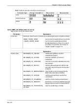
native rM2M_GetDate(&year=0, &month=0, &day=0, timestamp=0);

If no time stamp was transferred (timestamp=0), the date (year, month, day) is determined for the
current system time (in UTC). Alternatively, the date (year, month, day) is determined for the
transferred time stamp.

Parameter

Explanation

year

Variable to store the year - OPTIONAL

Note:

The year specified relates to the 21st century, i.e. the value 14 refers to

the year 2014.

month

Variable to store the month - OPTIONAL

day

Variable to store the day - OPTIONAL

timestamp

Time stamp for which the date should be determined

= 0: The date for the current system time (in UTC) is determined.
 > 0: The date for the transferred time stamp is determined.
       (The time stamp must be specified in seconds since 31.12.1999.)

Explanation

Return value

l

timestamp = 0: Seconds since 31.12.1999 (current system time in UTC)

l

timestamp > 0: The transferred time stamp is returned.

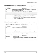
native rM2M_GetDateTime(datetime[TrM2M_DateTime]);

Reads the current time (in UTC) and date from the system

Parameter

Explanation

datetime

Structure for storing a detailed breakdown of the date and time (see "TrM2M_
DateTime" in chapter "Arrays with symbolic indices" on page 119
)

Explanation

Return value

l

OK, if successful

l

ERROR, if an invalid parameter was transferred

120

Rev. 05

Summary of Contents for myDatalogEASY V3

Page 1: ...300574 Rev 05 Cover Valid from l Firmware version 01v015 l Server version 49v011 l Hardware version 4 0 User manual myDatalogEASY V3 ...

Page 2: ......

Page 3: ... and precautionary measures for the GSM GPRS modem installation 21 4 4 3 2 Safety measures for installing the antenna 21 4 5 Overview 22 4 5 1 Block diagram 23 4 6 Intended use 24 4 7 General product information 24 4 8 Device labelling 25 4 9 Installation of spare and wear parts 26 4 10 Storage of the product 26 4 11 Warranty 27 4 12 Disclaimer 27 4 13 Obligation of the operator 27 4 14 Personnel ...

Page 4: ...ries 43 6 2 Scope of supply 43 6 3 Storage 44 6 4 Transport 44 6 4 1 Transporting power supply units 44 6 5 Return 46 Chapter 7 Installation 47 7 1 Dimensions 47 7 2 Assembling the myDatalogEASY V3 47 7 3 Inserting replacing the SIM card 53 7 4 Installing the myDatalogEASY V3 55 7 4 1 Wall mounting 56 7 4 2 Top hat rail assembly 57 7 4 3 Pipe assembly 58 7 5 Safety instructions for the cabling 59 ...

Page 5: ...sor supply VEXTRS232 71 7 6 8 4 Isolated switch contact NO CC 71 7 6 9 Technical details about energy management 71 7 6 10 Technical details about the energy supply 72 7 6 10 1 PSU413D AP 300524 73 7 6 10 2 PSU413D AP 300525 74 7 6 10 3 PSU713 BP 300526 74 7 6 10 4 PSU DC 300529 74 7 6 10 5 PSU AC 300558 75 7 6 10 6 PSU DC 300798 75 7 6 11 Technical details about the system time 75 Chapter 8 Initi...

Page 6: ... instrument 86 9 2 2 3 GPRS 87 Chapter 10 DeviceConfig 89 10 1 General 89 10 2 Prerequisites 89 10 3 Functional principle 90 10 4 Installation 91 10 5 Menu of the DeviceConfig 93 10 5 1 Settings 93 10 5 1 1 Options 93 10 6 Connecting a Device via USB 95 10 7 GSM tab 96 10 8 Log tab 98 10 9 Firmware tab 100 10 10 Features tab 101 Chapter 11 myDatanet server 103 11 1 Overview 103 11 1 1 Explanation ...

Page 7: ...eb based development environment rapidM2M Studio 117 13 2 rapidM2M Device API 118 13 2 1 Constants 118 13 2 2 Timer date time 119 13 2 2 1 Arrays with symbolic indices 119 13 2 2 2 Constants 119 13 2 2 3 Functions 119 13 2 3 Uplink 124 13 2 3 1 Arrays with symbolic indices 124 13 2 3 2 Constants 124 13 2 3 3 Callback functions 128 13 2 3 4 Functions 129 13 2 4 System 138 13 2 4 1 Arrays with symbo...

Page 8: ...bolic indices 177 13 2 11 2 Functions 177 13 2 12 Various 178 13 2 12 1 Arrays with symbolic indices 178 13 2 12 2 Constants 179 13 2 12 3 Functions 179 13 2 13 Console 185 13 2 14 SMS 186 13 2 14 1 Callback functions 186 13 2 14 2 Functions 186 13 2 15 External SIM 187 13 2 15 1 Arrays with symbolic indices 187 13 2 15 2 Functions 187 13 2 16 File transfer 188 13 2 16 1 Arrays with symbolic indic...

Page 9: ...208 13 2 21 3 Callback functions 209 13 2 21 4 Functions 209 13 3 Device Logic error codes 210 13 4 Syntax 213 13 4 1 General syntax 213 13 4 1 1 Format 213 13 4 1 2 Optional semicolons 213 13 4 1 3 Comments 213 13 4 1 4 Identifier 213 13 4 1 5 Reserved keywords 213 13 4 1 6 Numerical constants 214 13 4 1 6 1 Numerical integer constants 214 13 4 1 6 2 Numerical floating point constants 214 13 4 2 ...

Page 10: ...ssignment 219 13 4 5 6 Comparative operators 220 13 4 5 7 Boolean 220 13 4 5 8 Other 221 13 4 5 9 Priority of the operators 221 13 4 6 Statements 222 13 4 6 1 Statement label 222 13 4 6 2 Composite statements 223 13 4 6 3 Expression statement 223 13 4 6 4 Empty statement 223 13 4 6 5 Assert expression 223 13 4 6 6 Break 224 13 4 6 7 Continue 224 13 4 6 8 Do statement while expression 225 13 4 6 9 ...

Page 11: ...14 1 4 Attributes of the field definition 238 14 2 Example 241 14 3 Special values of the data types 243 Chapter 15 API 245 15 1 Frontend API 245 15 2 rapidM2M Playground 245 15 2 1 Overview 246 Chapter 16 Maintenance 247 16 1 General maintenance 247 16 2 Replacing the power supply unit 247 16 2 1 Charging the power supply unit 249 16 3 Power supply units with integrated energy store 251 Chapter 1...

Page 12: ...tennas 264 19 4 Power supply units 264 19 5 Charging devices and power supply units 265 19 6 Sensors 265 19 7 Other accessories 265 Chapter 20 Document history 267 Chapter 21 Glossary 275 Chapter 22 Contact information 277 12 Rev 05 ...

Page 13: ...Chapter 2 Declaration of conformity Chapter 2 Declaration of conformity Rev 05 13 ...

Page 14: ......

Page 15: ...ly on page 72 Supply or charging voltage 12 32VDC max 12W Housing Material Weight Protection class Dimensions WHD ABS PC housing cover 330g without power supply unit IP66 86 x 175 x 64mm without antenna Operating temperature 20 60 C Air humidity 15 90 rH non condensing Storage temperature 30 85 C Display Two colour LED with selectable function l Signalling the operating state controlled by the FW ...

Page 16: ...ded in Technical details about the system time on page 75 Internal sensors Internal housing temperature l Measurement range 20 60 C l Resolution 0 1 C Humidity in the housing l Measurement range 0 100 rH l Resolution 0 1 rH External temperature sensor 2 1 x PT100 1000 including auto detection Additional information is provided in Technical details about the PT100 1000 interface on page 66 Serial i...

Page 17: ...vided in Technical details about the outputs on page 69 Bluetooth 6 5 0 compatible low energy module USB interface 1 x mini B USB 2 0 slave for the connection to a PC The DeviceConfig configuration program must be installed on the PC or the web based development environment rapidM2M Studio must be used to enable communication with the myDatalogEASY V3 Additional information is provided in Technica...

Page 18: ...are only available if the RS485 interface is not used 2 In order for the external temperature sensor to be used the chargeable feature Activation code temperature input 300542 must be unlocked or order option Feature activation temperature input 300732 is required 3 In order for the RS232 interface to be used the chargeable feature Activation code RS232 300541 must be unlocked or order option Feat...

Page 19: ...iginal manual German must be referenced or the manufacturer contacted for clarification 4 2 Copyright The copying and distribution of this document as well as the utilisation and communication of its contents to others without express authorisation is prohibited Contraventions are liable to compensation All rights reserved 4 3 General descriptive names The use of general descriptive names trade na...

Page 20: ...particularly emphasised Note Indicates a situation that does not result in any injury to persons Note Information that supplements the specifications in the main text 4 4 2 General safety instructions WARNING Hazardous electric voltage can cause electric shock or burns Always switch off all of the used power supplies for the device before installing it completing any maintenance work or resolving ...

Page 21: ...rect grounding of external antennas l The device must not be operated in hospitals and or in the vicinity of medical equipment such as heart pacemakers or hearing aids l The device must not be operated in highly flammable areas such as petrol filling stations fuel storage sites chemical factories and explosion sites l The device must not be operated in the vicinity of flammable gases vapours or du...

Page 22: ...mbled before use see Assembling the myDatalogEASY V3 on page 47 Front of the myDatalogEASY V3 view of a device after assembly Rear of the myDatalogEASY V3 view of a device after assembly 1 Antenna connector 3 Cable screw connection cable diameter of 5 10 mm 2 Housing cover 4 Pressure compensation 22 Rev 05 ...

Page 23: ...ock diagram Block diagram of the myDatalogEASY V3 1 It is a DC DC converter with controllable output current A power supply unit e g PSU413D AP that is equipped with a rechargeable battery can thus be charged via the V Batt in output Rev 05 23 ...

Page 24: ... in the service area of one of these service providers You can find a list of all supported countries and associated service providers under www microtronics com footprint A Managed Service contract with Microtronics Engineering GmbH is required for use of the mobile data transmission see www microtronics com managedservice This includes the provisioning of the mobile communications connection via...

Page 25: ...EASY V3 is equipped with an integrated SIM chip for this purpose 1 The universal inputs 3 and 4 are only available if the RS485 interface is not used 2 In order for the external temperature sensor to be used the chargeable feature Activation code temperature input 300542 must be unlocked or order option Feature activation temperature input 300732 is required 3 In order for the RS232 interface to b...

Page 26: ...her all of the relevant data has now been transferred If your device does not include the option to initiate the transmission of temporarily stored measurement data you may have to wait until the next scheduled data transmission for all of the data to be sent to the myDatanet server This particularly applies to the interval connection type see rM2M_TxSetMode If the Interval wakeup connection type ...

Page 27: ...Ex regulations as well as safety requirements and regulations in order to avoid accidents shall be adhered to l for damages to persons or objects resulting from improper use For safety and warranty reasons all internal work on the instruments beyond from that involved in normal installation and connection must be carried out only by qualified Microtronics personnel or persons or companies authoris...

Page 28: ...ng and maintenance may only be completed by personnel who meet the following conditions l Qualified specialist personnel with the relevant training l Authorised by the facility operator Note Qualified personnel In the context of these instructions and the warnings on the product itself individuals responsible for the setup installation commissioning and operation of the product must have gained re...

Page 29: ...4 Data Descriptor defined by the customer that enables the use of the measurement data and configurations generated by the application Device Logic in connection with the interface of the myDatanet server see Data Descriptor on page 235 5 Client that accesses the interface of the myDatanet server via the web browser 6 Customer specific server that provides clients with their own interface The cust...

Page 30: ...ASY V3 and myDatanet server The application created by the customer must record the measurement values and create the data blocks that are to be saved The data blocks on the other hand are stored by the firmware of the myDatalogEASY V3 see rM2M_RecData The time of the synchronisation and the type of connection must also be determined by the application created by the customer Both of the API funct...

Page 31: ... selection of the containers helps to reduce the required data volume and associated costs 5 2 Functionality of the internal data memory Structure Circular buffer Total size 3MB Number of sectors 8 Sector size 393 216 Byte The internal data memory of the myDatalogEASY V3 is designed as a circular buffer with 8 sectors If the entire memory 3MB is full the sector with the oldest data is deleted full...

Page 32: ...ata memory if further data is recorded once 3MB has already been recorded Note Additional explanation on calculating the data volume to be saved To provide a clear and simple overview the following example assumes that the sectors can only record two complete data records 1 Free memory in sector 1 is not enough to record a full data record overhead data 32 Rev 05 ...

Page 33: ...instruction pragma amxcompress 0 3 The PAWN binary 256kB 10 configuration blocks 4000 Byte each 4 registration memory blocks 1kB each and measurement data 3MB are stored in the flash memory of the myDatalogEASY V3 To execute via the PAWN script engine the data area of the PAWN binary is decompressed if necessary and copied to the RAM The maximum size for the decompressed data area of the PAWN bina...

Page 34: ...EUPABLE The modem is logged into the GSM network and the system waits for the next connection attempt to be initiated The last connection attempt was successful and all of the data was transmitted As the modem is logged into the GSM network the connection establishment can also be initiated via the myDatanet server see myDatanet Server Manual 805002 RETRY The system waits 2min until the next conne...

Page 35: ...ed with a SIM chip that provides a mobile connection via a variety of international service providers see www microtronics com footprint This is completed automatically by the device 5 6 Determining the GSM UMTS LTE signal strength The internal update rate of the measurement value for the GSM UMTS LTE signal strength is dependent on the type of connection selected via the rM2M_TxSetMode function l...

Page 36: ...REG_SYS_OTP 1 readable Device Logic myDatanet server FLASH System information that is written once as part of the production process REG_SYS_FLASH 1 readable Device Logic myDatanet server FLASH System information that must be able to be changed during operation Application specific data REG_APP_OTP readable Device Logic myDatanet server writeable Device Logic FLASH Application specific information...

Page 37: ...w site is only created if the customer and application template were found on the myDatanet server and pipCtxAutocreate 1 or the field is missing l A site with the name specified in the pipCtx field was found on the server In this case the pipCtxAutocreate and pipCustomer fields are not relevant The device is assigned to the site even if it is located within a different customer if the application...

Page 38: ...stock RM2M_SIM_STATE_HOT Yes Valid contract RM2M_SIM_STATE_COLD No End of contract or violation of fair use policy RM2M_SIM_STATE_ DISCARDED No Device decommissioned As the previous table illustrates it is not possible to trigger the connection by Device Logic for the RM2M_ SIM_STATE_COLD and RM2M_SIM_STATE_DISCARDED states In this case the functions rM2M_ TxStart and rM2M_TxSetMode return error c...

Page 39: ...nfig configuration program see GSM tab on page 96 or must be set by the Device Logic via the rM2M_ SetExtSimCfg function In the current implementation using an external SIM card will not increase availability This means that in the event of any communication problems relating to the external SIM card the firmware will not automatically switch to the internal SIM chip This cost oriented approach he...

Page 40: ...nnection External SIM slot released External SIM card inserted Correct APN setting saved in the device SIM used 0 0 0 internal 0 0 1 0 1 0 0 1 1 1 0 0 internal 1 0 1 1 1 0 1 1 1 external The signalling of the connection status described in chapter Procedure in case of connection aborts on page 34 is extended by the EXTSIM signal when using an external SIM card Connection could be established durin...

Page 41: ...sure that a connection can be established via the external SIM card as previously mentioned the valid APN settings must be saved in the myDatalogEASY V3 and the chargeable Activation code VPN SIM 300539 feature must be released ACTIVE STARTED NOT ACTIVE WAKEUPABLE RETRY FAILED see Procedure in case of connection aborts on page 34 The current status can be read out at any time via the rM2M_TxGetSta...

Page 42: ......

Page 43: ...d thereafter will not be accepted 6 2 Scope of supply Note The power supply unit required for operation see Power supply units on page 264 and the antenna see Antennas on page 264 are not part of the standard scope of delivery and must be ordered separately The standard scope of delivery of the myDatalogEASY V3 300534 includes l myDatalogEASY V3 base unit l 2x cable screw connections cable diamete...

Page 44: ...mportant note Remove the power supply unit from the myDatalogEASY V3 prior to storage Store the measurement technology so that it is protected against corrosive or organic solvent vapours radioactive emissions as well as strong electromagnetic radiation 6 4 Transport Protect the myDatalogEASY V3 against heavy shocks bumps impacts or vibrations The original packaging must always be used for transpo...

Page 45: ...fore be observed in conjunction with transporting lithium batteries l Type of lithium battery l Lithium ion battery l Lithium metal battery l Battery energy content l If the energy content is within the exempt level this will make the transportation process easier l If the energy content is above the exempt level the battery is classed as a complete hazardous material in accordance with the releva...

Page 46: ...AC 300558 Lithium ions 3 33Wh UN3480 PSU DC 300798 Lithium ions 3 33Wh UN3480 6 5 Return Every return must be accompanied by a fully field out return form This return form is available in the service area of the myDatanet server An RMA number is mandatory for any returns and can be obtained from the Support Service Centre see Contact information on page 277 The return shipment of the myDatalogEASY...

Page 47: ... Dimensions depth view of a device after assembly 7 2 Assembling the myDatalogEASY V3 Important note l All wiring work must be performed in the de energised state l Ensure installation is completed correctly l Improper handling can cause injuries and or damage to the instruments l The myDatalogEASY V3 must not be operated in the field with the lid open l To ensure the housing is properly sealed ea...

Page 48: ...e screw connections cable diameter of 5 10 mm 6 Housing cover 1 Check that the content of the pack is complete The following step is only necessary if you want to use a customer specific SIM card 2 Insert the SIM card in the SIM slot as described in chapter Inserting replacing the SIM card on page 53 Obviously the first steps to open the housing and remove the power supply unit are not necessary N...

Page 49: ...agement hook and thus make it easier to insert the cable screw connection into the hole in the myDatalogEASY V3 base unit The engagement hook is not symmetrical One of the lugs on the engagement hook is longer Fig 1 preparing the cable screw connection Fig 2 preparing the cable screw connection 1 Engagement hook 3 Longer lug on the engagement hook 2 Locking nut Rev 05 49 ...

Page 50: ... single cable must be threaded through the cable screw connections to ensure the seal of the housing is not jeopardised Threading the connection cables in 1 Cable screw connection cable diameter of 5 10 mm 3 Connector plug 2x 2 pin 2x 3 pin 1x 6 pin 2 Connection cable of a sensor actuator or the supply or charging voltage 5 In accordance with the following figures thread the engagement hook with t...

Page 51: ...antenna see Connecting the GSM antenna on page 64 The antenna is not included in the scope of delivery and must be ordered separately 9 Insert the power supply unit The power supply unit is designed in such a way that it cannot be inserted incorrectly Note Note that all power supply units with an integrated and rechargeable energy store are delivered with a maximum charge of 30 in accordance with ...

Page 52: ...se unit 3 Housing cover 2 Delta PT M3 5x25 Torx 15 12 Check that the housing cover is positioned correctly on all sides and that no foreign materials have been trapped between the housing and housing cover Important note The manufacturer is not liable for any damage that is caused by housing covers that are not closed correctly The following step is only necessary if you are using an external supp...

Page 53: ...Strap to remove the power supply unit 1 Remove the four screws that secure the housing cover Now open the myDatalogEASY V3 Important note In the event of adverse weather conditions including rain or in a location where water can penetrate from above suitable measures must be implemented to protect the device from penetrating moisture when the housing cover is open 2 Remove the power supply unit fr...

Page 54: ... the cover of the SIM slot and the power supply unit The following step is not mandatory 7 Check whether the connection to the myDatanet server has worked correctly see Testing communication with the device on page 79 8 Close the housing cover The best option is to tighten the four screws crosswise torque 0 5Nm At the first screw 0 7Nm because the threads have to be shaped into the base part first...

Page 55: ...ainst contamination l The myDatalogEASY V3 is not approved for use in closed channels The installation site must be selected according to specific criteria The following conditions must be avoided in any case l Direct sunlight l Direct weather exposure rain snow etc l Objects that radiate intense heat maximum ambient temperature 20 60 C l Objects with a strong electromagnetic field frequency conve...

Page 56: ...e wall drill four 6 mm holes in the wall using the drill template as a guide in accordance with the dimensions in the diagram Step 2 of the wall mounting on page 56 If you want to use your own fastening screws you can use the drill guide provided in the equipment set to determine the position of the holes The diameters are then determined by the screws that are being used and any wall plugs that m...

Page 57: ...rx 15 included in the scope of delivery of 206 634 1 First attach the assembly loop 3 using the screws 2 included in the DIN rail mounting set for myDatanet housing 86x126 206 634 equipment set to the myDatalogEASY V3 see Step 1 of the top hat rail assembly on page 57 2 Place the assembly loop 3 onto the top edge of the top hat rail When turned slightly around the horizontal axis of the myDatalogE...

Page 58: ...d in the scope of delivery of 206 660 4 Cable binder included in the scope of delivery of 206 660 1 First attach the assembly loop 3 using the screws 2 included in the Pipe mounting kit for myDatanet housing 86x126 206 660 equipment set to the myDatalogEASY V3 see Step 1 of the pipe assembly on page 58 2 Position the myDatalogEASY V3 with the attached assembly loop 3 on the pipe and use the suppli...

Page 59: ...following warnings and information must be observed in addition to the warnings and information found in the individual chapters on the installation Further safety information is included in Safety instructions on page 19 Remove the power supply unit from the device before completing any wiring work Removing the power supply unit 1 Delta PT M3 5x25 Torx 15 3 Housing cover 2 Power supply unit 4 Str...

Page 60: ...nents that are sensitive to static l Wear an antistatic wristband that is grounded via a cable to discharge your body and keep it free of static electricity l Only touch components that are sensitive to electric charges in an antistatic working area If possible use antistatic mats and work pads 7 6 Electrical installation Important note Only qualified personnel should undertake the installation de...

Page 61: ...n 2x 3 pin 1x 6 pin 2 RS232 interface 7 pin JST connector 4 Cable screw connection cable diameter of 5 10 mm 1 SHIELD Cable shielding 2 GND Ground 3 RTS RTS line of the RS232 interface 4 CTS CTS line of the RS232 interface 5 RXD RXD line of the RS232 interface 6 TXD TXD line of the RS232 interface 7 VEXTRS232 Switchable sensor supply 3 3V Assignment of the RS232 interface Rev 05 61 ...

Page 62: ...e device from penetrating moisture when the housing cover is open 2 Remove the power supply unit from the myDatalogEASY V3 Use the strap provided to remove the power supply unit 3 Then connect your sensors and actuators with the universal inputs and outputs You will require a cable with a 7 pin JST connector to connect the sensors and actuators to the RS232 interfaces Ensure that no current is pre...

Page 63: ... have to be shaped into the base part first so that the housing cover is positioned evenly Important note Ensure that the seals are clean and intact before closing the housing cover Remove any impurities and or dirt The manufacturer shall not be liable for any damage to the device caused by leaky or faulty seals Closing the housing cover 1 myDatalogEASY V3 base unit 3 Housing cover 2 Delta PT M3 5...

Page 64: ...manently active for this purpose The use of VEXT is recommended for this purpose see sensor 1 in the connection example above The power consumption per input when the switch contact is closed can be up to 384µA due to the load of 10k086 7 6 2 Connecting the GSM antenna Important note To ensure the correct functionality only use antennas that are supplied by the manufacturer The standard antenna Po...

Page 65: ...lowing step is not mandatory 5 Check whether the connection to the myDatanet server has worked correctly see Testing communication with the device on page 79 7 6 3 Technical details about the universal inputs Note The universal inputs are not galvanically isolated 7 6 3 1 0 4 to 20mA mode Note Above 23 96mA the relevant input becomes highly resistive safety shutdown to prevent damage to the univer...

Page 66: ...additional link is required on two wire sensors see PT100 PT1000 2 wire on page 66 PT100 PT1000 3 wire PT100 PT1000 2 wire 7 6 5 Technical details about the RS485 interface Note l The RS485 interface corresponds to standard EIA 485 l The RS485 interface is only available if the universal inputs 3 and 4 are not being used The RS485 interface of the myDatalogEASY V3 includes an input common mode ran...

Page 67: ...M occurs in this case The GND potential difference must not exceed max 7V Higher voltages will damage the interface Temporary overvoltages ESD EFT and surge are however absorbed by protective circuits Note The common mode input voltage range of 7V 12V specified for the RS485 is determined from the max permissible GND potential difference 7V and the max permissible output voltage range of 0 5 V for...

Page 68: ...M Studio on page 111 Explanations regarding the functionality of the DeviceConfig configuration program is provided in chapter DeviceConfig on page 89 Access to the web based development environment rapidM2M Studio is included in the Microtronics Partner Program for which you can register free of charge at the following address https partner microtronics com The DeviceConfig configuration program ...

Page 69: ...ote The switchable sensor supply output is short circuit proof The output voltage can be varied in the range of 5 24V using the Device Logic see Vsens_On Output voltage characteristics subject to the load current for VOUT 5V Output voltage characteristics subject to the load current for VOUT 12V Rev 05 69 ...

Page 70: ...ject to the load current for VOUT 24V 7 6 8 2 Switchable sensor supply VEXT Note The switchable sensor supply output is short circuit proof The switchable sensor supply VEXT is applied to the main terminal block see Connecting the sensors actuators and power supply on page 60 Uout 3 3V Imax 180mA 70 Rev 05 ...

Page 71: ... the ERROR result if an attempt to establish the connection using the rM2M_TxStart function is made once this threshold is reached The rM2M_TxSetMode function also returns the ERROR result if an attempt to activate Interval wakeup or online mode is made The Device Logic is executed as intended once this threshold is reached The Device Logic execution is only stopped if the internal supply voltage ...

Page 72: ...ARGING_NORMAL The charge control is activated and the rechargeable battery is charged to the maximum voltage if the state of charge of the rechargeable battery for the power supply unit falls below 50 The charge control is then deactivated again This is designed to optimise the service life of the rechargeable battery l PM_CHARGING_SOLAR The rechargeable battery of the power supply unit is charged...

Page 73: ...contains a rechargeable battery PSU413D AP PSU413D AP a battery PSU713 BP a power supply unit and a rechargeable battery PSU AC or only a protective circuit PSU DC A list of compatible PSUs is included in the chapter Power supply units on page 264 An external supply or charging voltage is not required if the power supply unit is equipped with a battery 7 6 10 1 PSU413D AP 300524 V IN Optional Prot...

Page 74: ...am of the PSU413D AP 7 6 10 3 PSU713 BP 300526 V IN Not required Protective circuit V IN Capacity 13Ah 93 6Wh Type Li SOCl2 Rechargeable No Nominal voltage 7 2V Operating temperature 20 50 C Charging temperature Storage temperature 20 25 C Block diagram of the PSU713 BP 7 6 10 4 PSU DC 300529 V IN Required Protective circuit V IN DC Protection circuit Capacity Type Rechargeable no Nominal voltage ...

Page 75: ... voltage 3 7V Operating temperature 20 60 C Charging temperature 0 40 C Storage temperature 0 35 C Block diagram of the PSU DC 7 6 11 Technical details about the system time The myDatalogEASY V3 is equipped with a hardware real time clock that has its own buffer battery with an expected service life of 10 years The system time continues to run even if the power supply unit is removed This means th...

Page 76: ......

Page 77: ...only be placed into operation after completion and inspection of the installation Study the manual thoroughly before placing into operation to prevent faulty or incorrect configuration Utilise the manual to familiarise yourself with the operation of the myDatalogEASY V3 and the input screens of the myDatanet server before you begin with the configuration 8 4 Commissioning the system Note It is rec...

Page 78: ... power supply unit as described in the chapter Assembling the myDatalogEASY V3 on page 47 If a Device Logic has already been loaded in the device execute the operations provided in the Device Logic to trigger the establishment of a connection Note Note that all power supply units with an integrated and rechargeable energy store are delivered with a maximum charge of 30 in accordance with applicabl...

Page 79: ...enna see Connecting the GSM antenna on page 64 The antenna is not included in the scope of delivery and must be ordered separately 4 Establish a connection If no script has been loaded in the device yet this can be achieved by inserting the power supply unit as described in the chapter Assembling the myDatalogEASY V3 on page 47 If a Device Logic has already been loaded in the device execute the op...

Page 80: ...on 6 Complete all of the steps detailed in the chapter Assembling the myDatalogEASY V3 on page 47 This includes connecting the sensors Important note All wiring work must be performed in the de energised state 7 You can use the Reports of the myDatanet server to check the data transmission see myDatanet Server Manual 805002 The configuration of the Data Descriptor see Data Descriptor on page 235 i...

Page 81: ...206 803 included in the scope of supply The Switch_Init function can be used to determine whether the solenoid switch is evaluated by the firmware or Device Logic Report Operation by the user Operation Firmware Press and hold for at least 3 sec and then release Initiation of the transmission Device Logic Press Call up of the public function for which the index is transferred to the Switch_Init fun...

Page 82: ...erver Click on the name of the site in the list of sites to open the input screen for configuring the site see myDatanet Server Manual 805002 9 2 1 1 Site Customer Specifies to which customer the site is assigned symbol Assign site to another customer Name Site designation not relevant for the device or data assignment 2 50 characters Device S N Serial number of the device that is linked to the si...

Page 83: ...xt connection The file path is only displayed as long as the input screen for configuring the site has not been closed Data descriptor Input window for configuring the Data Descriptor see Data Descriptor on page 235 9 2 1 4 Configuration 0 Configuration 9 Note These configuration sections are only visible if the logical structure of the corresponding configuration data block was defined using the ...

Page 84: ...aken from the global server settings off The transfer volume alarm is deactivated individual The level at which the transfer volume alarm should be triggered can be entered in the adjacent field in KiB Offline alarm after alarm in the event that the device does not report for longer than the set time 00 00 alarm deactivated Title user alarm 1 Freely selectable title for user defined alarm 1 If the...

Page 85: ...ed are displayed in the dropdown list not assigned The default graphic is used to display the measurement data Name of a report template Name of the report template used to display the measurement data Change log configuration Selection of which changes to the configurations should be logged web api Changes that were implemented via the server interface or REST API are logged web device api Change...

Page 86: ...r of the instrument Instrument class The instrument class of the site and instrument must match for an instrument to be able to be connected to a site Once the instrument has been created via the server interface the instrument class can only be changed up until the first connection of the instrument to the server If an instrument class that does not match the actual class of the instrument is sel...

Page 87: ... the one on the device NOT RECOMMENDED Once Performs a single firmware update If no new firmware is available or the firmware was installed successfully the firmware update is automatically switched to OFF Ignore The firmware update is deactivated and no information is provided about available firmware updates Firmware type Released Only firmware versions that have successfully undergone internal ...

Page 88: ......

Page 89: ...ally adjusts to the relevant device that is connected In addition to the standard functions the tool also supports device specific processes e g calibration zero point adjustment The DeviceConfig enables you to complete the following tasks l Synchronisation of measurement data and configuration between device and server specifically for devices without GSM GPRS modem l Basic configuration of the d...

Page 90: ...ousing The manufacturer shall not be liable for any damage to the device for example caused by the ingress of water attributed to the fact that the housing was opened The configuration program DeviceConfig communicates directly with the myDatalogEASY V3 via a USB connection The functions provided with the DeviceConfig configuration program include l Switching between the integrated SIM chip and th...

Page 91: ...s 7 1 Execute the InstDeviceConfig exe file to start the installation process Note Only connect the device or USB BLE Adapter 300685 to your PC once the installation process has completed as the required drivers are only installed during this process DeviceConfig setup wizard Rev 05 91 ...

Page 92: ...owing drivers must be installed to ensure correct operation Installation of the USB drivers for the devices Installation of the drivers for the USB BLE Adapter Installation of the USB drivers for the devices on a M1 basis Installation of the USB drivers for the devices on a M2 M3 basis 92 Rev 05 ...

Page 93: ...cted can be specified and the automatic search for the available firmware versions can be activated or deactivated via the Settings Options menu item The USB radio transmitter 206 657 is required for myDatanet devices that are connected to the PC via a wireless M bus while the USB BLE Adapter 300685 is required for devices that are connected to the PC via Bluetooth Low Energy Information on whethe...

Page 94: ...adio transmitter 206 657 only visible when the automatic search is deactivated 2 Activates deactivates the automatic search for the USB BLE Adapter 300685 on all of the available COM ports 5 COM port that is connected with the USB BLE Adapter 300685 only visible when the automatic search is deactivated 3 Activates deactivates the automatic search for available firmware versions 94 Rev 05 ...

Page 95: ...SB 1 Start the DeviceConfig configuration program DeviceConfig 2 Connect the myDatalogEASY V3 to the PC using a USB cable 3 Select your device based on the serial number from the list of devices found List of devices found Rev 05 95 ...

Page 96: ... and the PIN code if required by the SIM card can be entered via this tab and transferred to the myDatalogEASY V3 Here it is possible to either enter the APN settings manually or to select one of the providers from the drop down list and thus to use the settings stored for the provider in the DeviceConfig Note The manufacturer assumes no liability for the correctness of the APN settings deposited ...

Page 97: ...IM slot 3 Drop down list for selecting the provider from which the external SIM card has been delivered Note The input fields for APN user and password for manual input of the APN settings are only displayed if the user defined entry has been selected in this drop down list 4 PIN code 5 Access point APN that should be used for the connection 6 User name for dial up via the access point 7 Password ...

Page 98: ...the log entries from the memory of the device 2 Time stamp of the log entry 6 Loads the log entries from the device 3 Log entry 7 Saves the loaded log entries as a tsv file 4 Parameter of the log entry 8 Window to display the loaded log entries The coloured highlighting indicates how crucial the log entry is The white informative log entries are only displayed when the detailed display of the log ...

Page 99: ...ht blue Blue Purple Grey Yellow Uncritical error Red Critical error Log tab with detailed view activated 1 Activates the detailed display of the log entries 3 Log entry that is always displayed 2 Informative log entry that is only visible if the detailed display is activated Rev 05 99 ...

Page 100: ...two available ways to update the firmware l Using a previously downloaded firmware package l By directly loading from the myDatanet server Firmware tab 1 Currently installed software version 3 The firmware is loaded directly from the server and installed on the device 2 Button to install a previously downloaded firmware package 100 Rev 05 ...

Page 101: ...t also offers an overview of the additional features that can be activated and which of these have already been activated Features tab 1 Feature has already been unlocked 3 Input field for the activation code 2 Feature is not unlocked 4 Button for confirming the activation code and unlocking the feature Rev 05 101 ...

Page 102: ......

Page 103: ... Opens the rapidM2M Playground 3 Displays the menu for adjusting the user settings and for logging out the currently active user 7 Switches to the Data exports area to configure the data export This tab is only visible if at least the licence for one export variant is available 4 Tabs to switch between the individual server areas 8 Opens the input screen to upload a XML file This tab is only visib...

Page 104: ...can be displayed as a Map and or the OpenStreetMaps map can be displayed The sites can be manually placed on the image file used as a map In the OpenStreetMaps map the sites are only displayed once GPS coordinates have been assigned to the site 2 Adds a new customer 104 Rev 05 ...

Page 105: ...hidden the selected tag is highlighted in colour and the title of the tag is crossed out Clicking the same mouse button again will remove the restriction 4 Opens the input screen for configuring the customer 5 Deletes the customer 6 Comment that can be entered in the configuration of the customer 7 If a default report was defined the default report is accessed by clicking on the name of the custom...

Page 106: ...a Map and or the OpenStreetMaps map can be displayed The sites can be manually placed on the image file used as a map In the OpenStreetMaps map the sites are only displayed once GPS coordinates have been assigned to the site 2 List of reports see Reports on page 107 3 List of sites applications see Site on page 82 106 Rev 05 ...

Page 107: ... on creating and handling the reports is provided in myDatanet Server Manual 805002 11 3 2 Map view The map view provides an overview of the geographic position of the sites Detailed instructions on operating and configuring map view are provided in myDatanet Server Manual 805002 11 4 Recommended procedure 11 4 1 Creating the site Note Some of the fields mentioned in the following chapters may be ...

Page 108: ...all up the list of existing sites applications Open the input window for creating a new site by clicking the Add new site application symbol enter the serial number of your device in the appropriate field and then click the Continue button Note The serial number is on the type plate of the device see Device labelling on page 25 Creating the site 1 Menu item to call up the list of existing sites ap...

Page 109: ... the site select the desired site type or the desired application from the drop down list and then click the Add button Completing site creation 1 Name of the site freely selectable 3 Add button 2 Drop down list of available applications templates and site types Rev 05 109 ...

Page 110: ......

Page 111: ...of the data measurement data configurations etc that is exchanged between myDatalogEASY V3 myDatanet server and external systems e g front ends connected via REST API l Portal view Simple front end that is supplied by the myDatanet server e g for fast prototype development and or provision of administrative data In addition to the dashboard see Project dashboard on page 113 for managing the projec...

Page 112: ...SB Operating system Windows 7 Windows 10 recommended MacOS 10 12 or higher Linux Fedora 32 Ubuntu 20 04 Archlinux 2020 06 01 Internet connection Required Required disk space No installation required Browser Google Chrome only 112 Rev 05 ...

Page 113: ...or the currently active user 5 Button for creating a new project 6 Buttons for filtering the list of the projects according to Recently used All my projects Projects shared by me Projects shared with me 7 Tile that contains all important information about an IoT project 8 List of the Collections All projects that are not assigned to another Collection Favourite projects Sample libraries provided b...

Page 114: ...2 Back to the project dashboard 3 Editor panel 4 Compiler results incl warnings and errors 5 Memory usage 6 Context sensitive help 7 Installs the current binaries of the project on the device and backend i e on the myDatanet server and opens the TESTbed 114 Rev 05 ...

Page 115: ...test 4 Watch panel 5 Information on the Backend under test i e the myDatanet server 6 Restarts the device logic installed on the device The device logic is reloaded onto the device for this purpose However any changes made in the CODEbed are not taken into account here This is only done again by clicking the button Install Run in the CODEbed 7 Button for displaying fading out additional panels 8 B...

Page 116: ......

Page 117: ... 1 2 Uploading a binary file If the Upload a compiled device logic entry was selected via the Device logic source list selection in the Control configuration section see Control on page 83 of the input screen for configuring the site a binary file that was for example previously created via the web based development environment rapidM2M Studio see rapidM2M Studio on page 111 can be uploaded to the...

Page 118: ...12 The required operation has exceeded the function capabilities ERROR_NOT_SUPPORTED 13 An option required by the function is not enabled on the CPU the function is not supported in this configuration ERROR_NO_MORE_TIMERS 14 The function requires a timer subscription but no more timer resources are available ERROR_NO_MORE_SEMAPHORES 15 The function requires a semaphore allocation but there are no ...

Page 119: ...ME 0b00000001 transferred time in local time 13 2 2 3 Functions native rM2M_GetTime hour 0 minute 0 second 0 timestamp 0 If no time stamp was transferred timestamp 0 the current system time in UTC is converted to hours minutes seconds Alternatively the transferred time stamp is converted to hours minutes seconds Parameter Explanation hour Variable to store the hours OPTIONAL minute Variable to sto...

Page 120: ... the date should be determined 0 The date for the current system time in UTC is determined 0 The date for the transferred time stamp is determined The time stamp must be specified in seconds since 31 12 1999 Explanation Return value l timestamp 0 Seconds since 31 12 1999 current system time in UTC l timestamp 0 The transferred time stamp is returned native rM2M_GetDateTime datetime TrM2M_DateTime ...

Page 121: ... 0 if the difference between the current time and time to be set is less than 5 sec l ERROR if invalid parameters were transferred l ERROR 1 if the time to be set is more than one day ahead of the current system time native rM2M_GetTimezoneOffset Returns the difference in seconds between the system time UTC and local time configured for the site on the myDatanet server This can be used to determin...

Page 122: ...n be created maximum number reached l OK if another error occurs see Return codes for general purposes in chapter Constants on page 118 native rM2M_TimerRemove funcidx Removes a 1s timer Parameter Explanation funcidx Index of the public function of the timer that should be removed Type of function public func Explanation Return value l OK if successful l ERROR if no valid index was transferred or ...

Page 123: ...stopped upon expiry of an interval with an interval of 0ms may be initialised Explanation Return value l OK if successful l ERROR if one of the following errors occurs l No valid index was transferred l An interval of 0ms was specified and the timer should be restarted automatically upon expiry of the timeout i e cyclical 0ms timer l Internal error l No additional timers can be created maximum num...

Page 124: ...has been established yet mcc MCC Mobile Country Code of the network used for the last connection 0 if no connection has been established yet mnc MNC Mobile Network Code of the network that was used for the last connection 0 if no connection has been established yet simstate Current SIM state see SIM state in chapter Constants on page 124 define TrM2M_GSMInfo cgmi 20 cgmm 20 cgmr 20 imei 16 imsi 16...

Page 125: ...up RM2M_TXMODE_ONLINE 2 Online Communication mode flags Configuration flags for the rM2M_TxSetMode function RM2M_TXMODE_SUPPRESS_SYNC 0b00000001 no auto sync with the server when the connection type is changed Connection status Return values of the rM2M_TxGetStatus function RM2M_TX_FAILED 0b0000000001 Connection establishment failed RM2M_TX_ACTIVE 0b0000000010 GPRS connection established RM2M_TX_S...

Page 126: ...NG external SIM not found RM2M_TXERR_MODEM_SIM_OTHER any other problem with SIM card e g internal SIM not found network related error GSM GPRS PDP etc RM2M_TXERR_MODEM_NETWORK 50 unspecified network related error RM2M_TXERR_MODEM_GSM_BAND_SEL GSM not available e g error with antenna RM2M_TXERR_MODEM_NETLOCK error registering within network e g not allowed RM2M_TXERR_MODEM_POSUPDATE error with GSM ...

Page 127: ...2M_TXERR_ETH_ITF_UP TCP IP stack error bringing itf up including dhcp network related Ethernet errors RM2M_TXERR_ETH_NETWORK 320 unspecified network related Ethernet error RM2M_TXERR_ETH_NETWORK_TIMEOUT timeout accessing network RM2M_TXERR_ETH_DHCP_TIMEOUT timeout receiving IP address from DHCP server TCP related Ethernet errors RM2M_TXERR_ETH_TCP 340 unspecified TCP related Ethernet error RM2M_TX...

Page 128: ...ion data Array that contains the data of the read data record len Length of the data area of the read data record in bytes max 1024 Byte timestamp Time stamp of the data record in UTC public func cfg Function to be provided by the script developer that is called if one of the configuration memory blocks has changed Parameter Explanation cfg Number of the changed configuration memory block starting...

Page 129: ...ations However it is recommended to call the rM2M_ TxStart function occasionally e g every 2h even in online mode since not all memory areas are automatically synchronised Parameter Explanation flags Configuration flags for the connection establishment Bit0 RM2M_TX_POSUPDATE If set the GSM position data is also updated Bit2 RM2M_TX_REFRESH_ CONFIG If set a connection to the maintenance server is a...

Page 130: ...rk as soon as this mode has been set RM2M_TXMODE_ONLINE The device does not disconnect the connection and continuously transmits the measurement data However every 7 days the connection is temporarily interrupted in order to verify the server assignment The connection is established as soon as this mode has been set Calling the rM2M_ TxStart function is not necessary flags Configuration flags for ...

Page 131: ...r Uplink on page 124 Explanation Return value Bit0 RM2M_TX_FAILED set if the last GPRS connection establishment failed Bit1 RM2M_TX_ACTIVE set when a GPRS connection is established Bit2 RM2M_TX_STARTED set when a connection establishment has been started Bit3 RM2M_TX_RETRY set during the waiting time until the next automatic retry in the event of connection problems Bit4 RM2M_TX_WAKEUPABLE set whe...

Page 132: ...ccurs native rM2M_GSMGetRSSI Returns the GSM UMTS LTE signal strength Important note Although this function will still be supported for the purpose of downward compatibility it should no longer be used for new projects The rM2M_ GetRSSI function should be used as an alternative Explanation Return value Signal strength in dBm maximum value range 128 127 GSM values range from 113 to 51 dBm native rM...

Page 133: ...ccurs see Return codes for general purposes in chapter Constants on page 118 native rM2M_LiveData const data len Transmits a data record as live data to the server Calling this function is only permissible if the device is in online mode and an active connection to the server is established Use the rM2M_Pack rM2M_ SetPacked or rM2M_SetPackedB functions to generate the data area Parameter Explanati...

Page 134: ...RROR if one of the following errors occurs l Memory area data len is invalid l More than 10 calls during one script run l Number of bytes to be saved 1024 Byte l FLASH write process not successful l The time stamp transfer parameter is more than 5 minutes in the future l OK if another error occurs see Return codes for general purposes in chapter Constants on page 118 native rM2M_ReadData recidx fu...

Page 135: ...OK if successful l OK if an error occurs see Return codes for general purposes in chapter Constants on page 118 Note Additional explanation on the type of storage If Bit 0 was not set default the non volatile storage of the configuration memory block in the FLASH is initiated when the rM2M_CfgWrite function is called If Bit0 was set Bit0 RM2M_CFG_VOLATILE the configuration memory block is saved in...

Page 136: ...e position where the data should be written data Array that contains the data that should be written in the configuration memory block size Number of bytes that should be written in the configuration memory block Explanation Return value l OK if successful l ERROR_MEM if enough temporary memory RAM is not currently available can occur if RAM in a volatile manner is selected as the type of storage ...

Page 137: ... Return value l Size of the memory used in the configuration memory block l ERROR_MEM if enough temporary memory RAM is not currently available can occur if RAM in a volatile manner is selected as the type of storage for several configuration memory blocks l OK if another error occurs see Return codes for general purposes in chapter Constants on page 118 native rM2M_CfgDelete cfg Deletes all of th...

Page 138: ...118 13 2 4 System 13 2 4 1 Arrays with symbolic indices TEasyV3_SysValue Internal measurement values Temp Internal housing temperature in 0 1 C RH Humidity in the housing in 0 1 rH define TEasyV3_SysValue Temp RH 13 2 4 2 Constants Numbers of the universal inputs UI_CHANNEL1 0 Universal input 1 UI_CHANNEL2 1 Universal input 2 UI_CHANNEL3 2 Universal input 3 UI_CHANNEL4 3 Universal input 4 Number o...

Page 139: ...MP_MODE_CONT_CONV The Temp_GetValue function always supplies the last valid temperature value until the PT100 1000 interface is closed by the Temp_ Close function Parameter Explanation temp Number of the PT100 1000 interface is always 0 for the myDatalogEASY V3 mode TEMP_MODE_SINGLE_ CONV The temperature is only measured once after the Temp_Init function is called TEMP_MODE_CONT_CONV The temperatu...

Page 140: ...the temperature module in 0 1 C Explanation Return value l OK if successful l ERROR_FEATURE_LOCKED if the specified interface on the device is not released l OK if another error occurs see Return codes for general purposes in chapter Constants on page 118 native EasyV3_GetSysValues values TEasyV3_SysValue len sizeof values Reads the last valid values for the Internal housing temperature and Air hu...

Page 141: ... be read get packed RM2M_PACK_BE 0b00000010 Use Big endian format RM2M_PACK_U8 0b00010000 8 bit unsigned RM2M_PACK_S8 0b10010000 8 bit signed RM2M_PACK_U16 0b00100000 16 bit unsigned RM2M_PACK_S16 0b10100000 16 bit signed RM2M_PACK_U32 0b01000000 32 bit unsigned RM2M_PACK_S32 0b11000000 32 bit signed RM2M_PACK_F32 0b01000000 32 bit float Rev 05 141 ...

Page 142: ...ue should be written value Value that should be written in the array size Number of bytes that should be used for the value to be written bigendian Settings for the byte sequence that should be used when writing the value true Big endian is used false Little endian is used Explanation Return value l OK if successful l OK if an error occurs see Return codes for general purposes in chapter Constants...

Page 143: ...rea for a data record or a configuration pos Byte offset within the array to determine the position where the data block should be written block Data block that should be written in the array size Number of bytes that should be written in the array by the data block Explanation Return value l OK if successful l OK if an error occurs see Return codes for general purposes in chapter Constants on pag...

Page 144: ...hould be read value Variable to store the data to be read size Number of bytes that should be read bigendian Specifies how the packed data must be interpreted true The data is saved in Big endian format in the array false The data is saved in Little endian format in the array Explanation Return value l OK if successful l OK if an error occurs see Return codes for general purposes in chapter Consta...

Page 145: ...hould be used as a data area for a data record or a configuration pos Byte offset within the array to determine the position from which the data should be read block Array to store the data to be read size Number of bytes that should be read Explanation Return value l OK if successful l OK if an error occurs see Return codes for general purposes in chapter Constants on page 118 Rev 05 145 ...

Page 146: ...ld be read value Set packed Value that should be written in the array Get packed Value that should be read from the array type Configuration flags for the function Bit0 Select Set packed Get packed 0 value should be written 1 value should be read Bit1 Byte order 0 Little endian format 1 Big endian format Bit2 3 reserved for extensions Bit4 7 Data type 1 8 bit unsigned 2 16 bit unsigned 4 32 bit un...

Page 147: ...the RS485_Init function RS485_1_STOPBIT 0b0000000000000001 1 stop bit RS485_2_STOPBIT 0b0000000000000010 2 stop bit RS485_PARITY_NONE 0b0000000000000000 no parity RS485_PARITY_ODD 0b0000000000000100 odd parity RS485_PARITY_EVEN 0b0000000000001000 even parity RS485_7_DATABIT 0b0000000000000000 7 data bits RS485_8_DATABIT 0b0000000000010000 8 data bits RS485_FLOW_NONE 0b0000000000000000 no flow cont...

Page 148: ...len Function to be provided by the script developer that is called when characters are received via the RS485 interface Parameter Explanation data Array that contains the received data len Number of received bytes 148 Rev 05 ...

Page 149: ...even parity 2 even parity Bit 4 5 0 7 data bits 1 8 data bits Bit 6 7 0 no flow control 1 RTS CTS handshake Bit 8 0 full duplex mode 1 half duplex mode Note You can also use the predefined constants for this parameter see Configuration of the RS232 interface in the chapter Constants on page 147 The constants can also be combined using the or conjunction funcidx Index of the public function for the...

Page 150: ...er Explanation rs232 Number of the RS232 interface is always 0 on the myDatalogEASY V3 Note You can also use the predefined constant RS232_ITF1 for this parameter data Array that contains the data to be sent len Number of bytes to be sent Explanation Return value l Number of processed bytes if successful Note If the number of processed bytes deviates from the passed number of bytes to be sent the ...

Page 151: ... rxbuf Static byte array that should be used as a buffer to receive characters via the RS232 interface rxlen Size of the receiving buffer in byte Note If the function is called up again and the size is set to 0 during the process then the system switches back to the integrated buffer 256 bytes The transferred static byte array can then be used by the script again txbuf Static byte array that shoul...

Page 152: ... 8 data bits Bit 6 7 0 no flow control 1 RTS CTS handshake Bit 8 0 half duplex mode 1 full duplex mode Bit 9 0 no load resistance 1 120Ω load resistance Note You can also use the predefined constants for this parameter see Configuration of the RS485 interface in the chapter Constants on page 147 The constants can also be combined using the or conjunction funcidx Index of the public function for th...

Page 153: ...Parameter Explanation rs485 Number of the RS485 interface is always 0 for the myDatalogEASY V3 Note You can also use the predefined constant RS485_ITF1 for this parameter data Array that contains the data to be sent len Number of bytes to be sent Explanation Return value l Number of processed bytes if successful Note If the number of processed bytes deviates from the transferred number of bytes to...

Page 154: ...byte array that should be used as a buffer to receive characters via the R485 interface rxlen Size of the receiving buffer in byte Note If the function is called up again and the size is set to 0 during the process then the system switches back to the integrated buffer 256 bytes The transferred static byte array can then be used by the script again txbuf Static byte array that should be used as a ...

Page 155: ...umber of registration memory blocks RM2M_REG_NUM_REGS 5 Error codes for the registration memory block access operations RM2M_REG_ERROR_TOKENMEM 101 Not enough tokens were provided RM2M_REG_ERROR_INVAL 102 Invalid character inside JSON string RM2M_REG_ERROR_PART 103 The string is not a full JSON packet more bytes expected RM2M_REG_ERROR_NOMEM 200 memory allocation failed RM2M_REG_ERROR_NUMTOKENS 20...

Page 156: ...stration memory blocks is provided in chapter Registration memory blocks on page 36 Parameter Explanation reg Registration memory block index The following registration memory blocks require an initialisation l RM2M_REG_APP_STATE Application specific volatile data e g current device status flags Configuration flags to be set deleted Bit0 Type of storage 0 invalid currently not supported RM2M_REG_V...

Page 157: ...see Error codes for the registration memory block access operations in chapter Constants on page 155 native rM2M_RegGetValue reg const name Float Fixed _ value tag tagof value reads a value from a registration memory block Detailed information on the registration memory blocks is provided in chapter Registration memory blocks on page 36 Parameter Explanation reg Index of the registration memory bl...

Page 158: ... memory block access operations in chapter Constants on page 155 native rM2M_RegSetValue reg const name Float Fixed _ value tag tagof value Writes a value into a registration memory block Detailed information on the registration memory blocks is provided in chapter Registration memory blocks on page 36 Parameter Explanation reg Index of the registration memory block see Indices of the registration...

Page 159: ...her error occurs see Error codes for the registration memory block access operations in chapter Constants on page 155 native rM2M_RegDelKey reg const name Searches for an entry based on its name and deletes the entry from the registration memory block Detailed information on the registration memory blocks is provided in chapter Registration memory blocks on page 36 Parameter Explanation reg Index ...

Page 160: ...cell in the receiving range mcc MCC Mobile Country Code of the GSM cell mnc MNC Mobile Network Code of the GSM cell lac LAC Location Area Code of the GSM cell cellid Cell ID of the GSM cell rssi Detected GSM level dBm for the GSM cell ta TA Timing Advance of the GSM cell currently always 0 define TrM2M_GSMPos mcc mnc lac cellid rssi ta TrM2M_PosUpdateGSM Information about a GSM cell in the receivi...

Page 161: ...mcc MCC Mobile Country Code of the GSM cell mnc MNC Mobile Network Code of the GSM cell lac LAC Location Area Code of the GSM cell cid Cell ID of the GSM cell rsrp Reference Signal Received Power dBm define TrM2M_PosUpdateLTE type stamp mcc mnc lac cid rsrp TNMEA_GGA Information position height above sea level and accuracy extracted from a GGA data record Lat geographical latitude in degrees resol...

Page 162: ... sea level invalid RM2M_NMEA_ERR_SAT_USED 7 Number of satellites used invalid RM2M_NMEA_ERR_QUAL 8 GPS quality indication not supported NMEA quality indicator RM2M_NMEA_FIX_NOK 0 invalid no fix RM2M_NMEA_FIX_GPS 1 Non differential GPS fix RM2M_NMEA_FIX_DGPS 2 Differential GPS fix RM2M_NMEA_FIX_PPS 3 Precise positioning service PPS RM2M_NMEA_FIX_RTK 4 Real time kinematic RTK RM2M_NMEA_FIX_FLOATRTK ...

Page 163: ... 180 west 0 Zero meridian Greenwich 180 000 000 180 east Elev Height above sea level in meters Valid range 999 9999 Qual Quality indicator GPS quality indicator RM2M_NMEA_FIX_NOK invalid no fix RM2M_NMEA_FIX_GPS non differential GPS fix RM2M_NMEA_FIX_DGPS differential GPS fix RM2M_NMEA_FIX_PPS Precise positioning service PPS RM2M_NMEA_FIX_RTK Real time kinematic RTK RM2M_NMEA_FIX_FLOATRTK Float re...

Page 164: ...nts on page 162 1 Contains the type of decoded NMEA data record see List of supported NMEA data records in chapter Constants on page 162 2 n Dependent on type of decoded NMEA data record For a type RM2M_NMEA_RECORD_GGA data record the remaining structure is the same as the TNMEA_GGA structure 2 Lat 3 Long 4 Alt 5 Qual 6 SatUsed 7 HDOP len Size in cells of the buffer to record the decoded data OPTI...

Page 165: ...on is transmitted to the myDatanet server and can for example be read out via the API see API on page 245 Parameter Explanation Sentence NMEA data record from a GPS receiver starting with the character The following data records are currently supported l GPGGA location specification fix information Important note The strings must be terminated 0 immediately after the checksum Explanation Return va...

Page 166: ...o store the quality indicator GPS quality indicator OPTIONAL RM2M_NMEA_FIX_NOK invalid no fix RM2M_NMEA_FIX_GPS non differential GPS fix RM2M_NMEA_FIX_DGPS differential GPS fix RM2M_NMEA_FIX_PPS Precise positioning service PPS RM2M_NMEA_FIX_RTK Real time kinematic RTK RM2M_NMEA_FIX_FLOATRTK Float real time kinematic RM2M_NMEA_FIX_EST Estimated fix dead reckoning coupled navigation RM2M_NMEA_FIX_MA...

Page 167: ...new sGSMPos TrM2M_PosUpdateGSM if type RM2M_POSUPDATE_TYPE_GSM rM2M_EnumPosUpdate idxEnum sGSMPos sizeof sGSMPos Parameter Explanation nEnum Variable to store the number of available cell network information entries idxEnum Index of the cell network information entry whose type should be determined or that should be read by the system Either the type parameter or the two buf and len parameters are...

Page 168: ... of GSM UMTS LTE cells for which valid information is saved to the device posidx 0 Number of the GSM UMTS LTE cell information block that should be read pos posidx 0 Not required posidx 0 Structure for storing the information about a GSM UMTS LTE cell in the receiving range see TrM2M_GSMPos in chapter Arrays with symbolic indices on page 160 Explanation Return value posidx 0 Number of GSM UMTS LTE...

Page 169: ...3661977236758134308 2 π M_2_SQRTPI 1 12837916709551257390 2 sqrt π M_SQRT2 1 41421356237309504880 sqrt 2 M_SQRT1_2 0 70710678118654752440 1 sqrt 2 Helpful constants native fround Float x Commercially rounds the transferred float Parameter Explanation x Float that should be rounded Explanation Return value Commercially rounded integral value native min value1 value2 Supplies the smaller of the two ...

Page 170: ...mit Explanation Return value l value if the value is between min and max l min is the value is less than min l max if the value is greater than max native swapchars c Swaps the order of the bytes Parameter Explanation c Value for which the bytes should be swapped over Explanation Return value Value for which the bytes in parameter c are swapped over the lowest byte becomes the highest byte The mod...

Page 171: ... a whole number native Float sqrt Float x Root x x 0 native Float ceil Float x Smallest whole number that is not smaller than x native Float floor Float x Largest whole number that is not larger than x native Float fabs Float x Absolute value x native Float ldexp Float x n x 2n native Float frexp Float x n Breaks down x into a normalised mantissa in the range 1 2 1 that is supplied as the result a...

Page 172: ...meter Explanation dest Array to store the formatted result maxlength Maximum number of characters that the array dest can store format The format character string to be used Explanation Return value l 1 in the event of a fault l Number of characters that would have been written if the array dest had been long enough without 0 The array dest is always assigned a final zero The length of the array d...

Page 173: ...ring2 Parameter Explanation string1 The two character strings that are to be compared string2 length The maximum number of characters that should be taken into consideration during the comparison OPTIONAL Explanation Return value l 1 string1 string 2 l 0 both of the character strings are the same at least the length that is taken into account l 1 string1 string 2 native strchr const string char Se...

Page 174: ...tring that should be searched string2 Character string of permitted characters Explanation Return value l Length of string1 if no permitted characters are found l Position of the first character in the character string that should be searched that is not included in the character string of permitted characters native strcspn const string1 const string2 Searches for the position of the first charac...

Page 175: ...g2 Searches character string2 in character string1 Parameter Explanation string1 Character string that should be searched string2 Character string that the search should be for Explanation Return value l 1 if character string2 that is being searched for is not included in string1 l Array index where character string2 that is being searched for starts in string1 native strtol const string base Conv...

Page 176: ...should be converted to lower case Explanation Return value The lower case variant of the transferred character if available or the unchanged character code of c if the letter c does not have a lower case equivalent native toupper c Converts a character into upper case Parameter Explanation c Character that should be converted to upper case Explanation Return value The upper case variant of the tra...

Page 177: ...lated modbus CRC16 of the transferred data Parameter Explanation data Array that contains the data for which the CRC16 should be calculated len Number of bytes that must be taken into consideration during the calculation initial Initial value for calculating the CRC16 OPTIONAL Explanation Return value Calculated CRC16 native CRC32 data len initial 0 Returns the calculated Ethernet CRC32 of the tra...

Page 178: ...rameter Explanation data Array that contains the data for which the MD5 hash should be calculated len Number of bytes that must be taken into consideration during the calculation hash Array to store the calculated 128 bit hash value ctx Context structure for the MD5 calculation OPTIONAL Explanation Return value 13 2 12 Various 13 2 12 1 Arrays with symbolic indices TablePoint Two column reference ...

Page 179: ... define TrM2M_Id string 50 module 10 hwmajor hwminor sn 8 fwmajor fwminor ctx 50 TRTM_Data Information regarding the runtime measurement runtime Determined runtime in ms instructions Number of executed pawn instructions tmp For internal use no write access permitted define TRTM_Data runtime instructions tmp 3 13 2 12 2 Constants Error codes for the CalcTable and CalcTableF functions const TAB_ERR_...

Page 180: ...son to the implementation in pawn A script module can contain several native functions After calling up this function the native functions contained in the script module can be used in the same way as the standard functions available in the pawn engine Parameter Explanation mod Byte array that contains the script module to be loaded Explanation Return value l OK if successful l ERROR if an error o...

Page 181: ...values are written in the runtime and instructions elements of the transferred structure to record the information regarding a runtime measurement Parameter Explanation measurement Structure for recording the information regarding a runtime measurement Important note This structure must be persistent from calling up rtm_ start to calling up rtm_stop Explanation Return value l OK if successful l ER...

Page 182: ... Return value l OK if the relevant value was found l TAB_ERR_FLOOR if the searched value is lower than the first table entry value contains the first table entry l TAB_ERR_CEIL if the searched value is higher than the last table entry value contains the last table entry l OK if another error occurs see Return codes for general purposes in chapter Constants on page 118 Note Additional explanation o...

Page 183: ...the function only has one transfer parameter older include file is being used and for compatibility reasons therefore returns OK instead of the size of the structure for storing the information native heapspace Supplies the free memory capacity to the heap Explanation Return value The free memory capacity to the heap The stack and the heap have a joint memory area so that this value specifies the ...

Page 184: ...nation arg The sequence number of the argument Use 0 for the first argument index Index if arg refers to an array value Value to which the argument should be set Explanation Return value l true if the value could be set l false if the argument or index are invalid This function sets an argument in a variable argument list If the argument is an array the index specifies the index of the required ar...

Page 185: ...nted characters l ERROR if not successful native setbuf buf size Provides the firmware with a buffer from the RAM area reserved for the script that is used to output strings via the printf function When this function is called up the system switches from the 256 byte buffer integrated in the firmware to the transferred buffer Parameter Explanation buf Static byte array that should be used as a buf...

Page 186: ...2M_SmsInit funcidx config Initialises SMS receipt Parameter Explanation funcidx Index of the public function that should be called up if an SMS has been received Type of function public func const SmsTel const SmsText Important note If an SMS that is longer than 160 characters is received it is discarded immediately The specified public function is not called up config Reserved for extensions Expl...

Page 187: ...cfg Structure that contains the configuration data for the external SIM card see TrM2M_SIMCfg in chapter Arrays with symbolic indices on page 187 len Size in cells of the structure that contains the configuration data OPTIONAL Explanation Return value l Size in cells of the structure used to store the configuration data l ERROR if the address and or length of the info structure are invalid outside...

Page 188: ...0001 File can be read by the server FT_FLAG_WRITE 0x0002 File can be written by the server FT_FLAG_NODE 0x0004 file nodes required to entitle the server to create a new file FT_FLAG_SYSTEM 0x0008 System file cannot be used by the script File transfer command FT_CMD_NONE 0 FT_CMD_UNLOCK 1 File transfer session terminated The server releases the block again FT_CMD_LIST 2 The server requests the prop...

Page 189: ... properties of the file that should be newly created Structure Offset Bytes Explanation 0 4 Time stamp of the file 8 4 File size in byte 12 4 Ethernet CRC32 of the file 16 2 File flags 18 256 File name l FT_CMD_WRITE Array that contains the data received from the myDatanet server len This parameter is only relevant when the following file transfer commands are received l FT_CMD_READ Number of byte...

Page 190: ...nsfer commands see File transfer commands in chapter Constants on page 188 must be handled by this public function Explanation Return value l OK if successful l OK if an error occurs see Return codes for general purposes in chapter Constants on page 118 native FT_Unregister id Removes a file from the registration The file is no longer available for the file transfer Parameter Explanation id Unique...

Page 191: ... flags in chapter Constants on page 188 Explanation Return value l OK if successful l OK if an error occurs see Return codes for general purposes in chapter Constants on page 118 native FT_SetPropsExt id props TFT_Info len sizeof props Sets the properties of a file extended format Important note This function must be called up following receipt of a FT_CMD_LIST command Parameter Explanation id Uni...

Page 192: ...ile that the myDatanet server wants to write It is a new file if the transferred unique identification number id parameter refers to a file node In this case an unique identification number newid parameter must be assigned to the new file The new file must also be registered via the FT_ Register function The file properties that were transmitted by the system to the callback function see Callback ...

Page 193: ...mand Parameter Explanation id Unique identification with which the file is referenced specified during registration len Number of written bytes Explanation Return value l OK if successful l OK if an error occurs see Return codes for general purposes in chapter Constants on page 118 native FT_Error id Used to display a file handling error and terminates any file command Parameter Explanation id Uni...

Page 194: ...2 Counter UI_CHT_SI_DFREQ 3 Frequency UI_CHT_SI_DPWM 4 PWM UI_CHT_SI_A020MA 5 0 4 20mA UI_CHT_SI_A002V 6 0 2V UI_CHT_SI_A010V 7 0 10V UI_CHT_SI_DIRECT 8 Direct corresponds to 0 2V mode on the myDatalogEASY V3 Sample rate in Hz for the measurement UI_SAMPLE_RATE_2 2 UI_SAMPLE_RATE_4 4 UI_SAMPLE_RATE_8 8 UI_SAMPLE_RATE_16 16 UI_SAMPLE_RATE_32 32 UI_SAMPLE_RATE_64 64 UI_SAMPLE_RATE_128 128 194 Rev 05...

Page 195: ...Universal input deactivated UI_CHT_SI_DIGITAL Digital max 32V low 0 99V high 2 31V load 10k086 UI_CHT_SI_DCTR Counter min pulse length 1ms load 10k086 UI_CHT_SI_DFREQ Frequency 1 1000Hz 10k086 UI_CHT_SI_DPWM PWM 1 99 max 100Hz min pulse length 1ms load 10k086 UI_CHT_SI_A020MA 0 4 20mA Resolution 6 3µA max 23 96mA load 96Ω UI_CHT_SI_A002V 0 2V Resolution 610µV max 2 5V load 10k086 UI_CHT_SI_A010V 0...

Page 196: ... system Detailed information on the universal inputs is provided in chapter Technical details about the universal inputs on page 65 Parameter Explanation temp Number of the universal input starting with 0 for UI 1 Note You can also use the predefined constants for this parameter see Numbers of the universal inputs in the chapter System on page 138 value Variable to store the measurement value to b...

Page 197: ...tion Return value l OK if successful l ERROR if an invalid parameter was transferred Note The sample rate for the universal inputs operated in Counter Frequency or PWM modes is not relevant You can use the lowest possible value for the sample rate if you operate all of the universal inputs in these modes and do not operate the isolated switch contact in pulse min mode native UI_ResetCounter channe...

Page 198: ...witchable sensor supply VOUT The output voltage 5 24V can be selected via the Mode parameter Detailed information on the switchable sensor supply is provided in chapter Switchable sensor supply VOUT on page 69 Parameter Explanation mode Selection of the output voltage VOUT 5000 24000 mV Explanation Return value l OK if successful l OK if an error occurs see Return codes for general purposes in cha...

Page 199: ...if successful l OK if an error occurs see Return codes for general purposes in chapter Constants on page 118 native Ext3V3_Off Deactivates the switchable 3 3V supply voltage VEXT Detailed information on the switchable 3 3V supply voltage is provided in chapter Switchable sensor supply VEXT on page 70 Explanation Return value l OK if successful l OK if an error occurs see Return codes for general p...

Page 200: ...tal output DIGOUT_FREQ Frequency output DIGOUT_PWM PWM output DIGOUT_IMPULSE_PER_ MINUTE Pulse min DIGOUT_IMPULSE_ONCE Single output of x pulses cfg1 DIGOUT_OFF Not used DIGOUT_DIG Not used DIGOUT_FREQ Pulse duty factor 1 100 default 50 DIGOUT_PWM Frequency 0 1000Hz default 100Hz DIGOUT_IMPULSE_PER_ MINUTE Pulse duration Dependent on the sample rate of the universal inputs1 default 100ms DIGOUT_IM...

Page 201: ...solated switch contact NO CC Detailed information on the isolated switch contact is provided in chapter Isolated switch contact NO CC on page 71 Parameter Explanation digout Number of the digital output isolated switch contact is always 0 for the myDatalogEASY V3 Explanation Return value l OK if successful l OK if an error occurs see Return codes for general purposes in chapter Constants on page 1...

Page 202: ... that should be issued per minute DIGOUT_IMPULSE_ONCE Number of pulses that should be issued Explanation Return value l OK if successful l OK if an error occurs see Return codes for general purposes in chapter Constants on page 118 Note Additional explanation on Pulse min mode DIGOUT_IMPULSE_PER_MINUTE Note that the maximum number of pulses that can be issued per minute is dependent on the pulse d...

Page 203: ...3V3_Off Deactivates the switchable 3 3V supply voltage VEXTRS232 Detailed information on the switchable 3 3V supply voltage VEXTRS232 is provided in chapter Switchable sensor supply VEXTRS232 on page 71 Explanation Return value l OK if successful l OK if an error occurs see Return codes for general purposes in chapter Constants on page 118 13 2 19 LED 13 2 19 1 Constants Selection of whether the t...

Page 204: ... successful l ERROR if an invalid parameter was transferred native Led_Close Deactivates the two colour LED The two colour LED cannot be controlled by the firmware or the script functions Explanation Return value OK if successful native Led_On bool red bool green The two colour LED consists of a red and a green LED that can be switched on separately by this function If both LEDs are switched on si...

Page 205: ...ns switched off 0 The green LED flashes until it is deliberately switched off 0 Number of times the green LED should flash Explanation Return value l OK if successful l ERROR if an invalid parameter was transferred native Led_Flash red green Enables the two colour LED to briefly flash every 500ms The two colour LED consists of a red and a green LED If both LEDs are used the two colour LED briefly ...

Page 206: ...mber of times the green LED should flicker Explanation Return value l OK if successful l ERROR if an invalid parameter was transferred 13 2 20 Solenoid switch 13 2 20 1 Constants Selection of whether the solenoid switch is evaluated by the firmware or script Configuration options for the Switch_Init function SWITCH_MODE_INTERNAL 0 evaluation by the FW SWITCH_MODE_SCRIPT 1 evaluation by the script ...

Page 207: ...which the index was transferred to the Switch_Init function is called funcidx Index of the public function that should be executed in the event of a state change of the button only necessary if mode SWITCH_MODE_SCRIPT Type of function public func key Explanation Return value l OK if successful l OK if an error occurs see Return codes for general purposes in chapter Constants on page 118 native Swi...

Page 208: ... VIn VBatt SOC PIn ChargingMode Description 16 13 2 21 2 Constants Charging mode PM_CHARGING_OFF 0 Charge control deactivated PM_CHARGING_NORMAL 1 charge if state of charge 50 PM_CHARGING_SOLAR 2 always charge when possible and sufficient input voltage V IN 16V is available Type of power supply unit PM_BATT_TYPE_NONE 0 No battery or external power supply PM_BATT_TYPE_NORMAL 1 Battery only discharg...

Page 209: ...M_CHARGING_OFF Charge control deactivated PM_CHARGING_NORMAL Charge if the state of charge of the rechargeable battery is 50 PM_CHARGING_SOLAR Charge continuously if possible and the supply or charging voltage V IN is above 16V Explanation Return value l OK if successful l ERROR if an invalid parameter was transferred native PM_BackupInit funcidx Activates malfunction monitoring for the supply or ...

Page 210: ...Resetting the Coulomb counter that can be used for the application 0 no action PM_CC_RESET Counter reset Explanation Return value Depleted electric charge mAs since the last reset of the Coulomb counter that can be used for the application 13 3 Device Logic error codes If an error occurs while executing the Device Logic the corresponding error code is entered in the device log and the Device Logic...

Page 211: ...urs Device Logic was restarted 5 SCRIPT SOFT ERROR 3 Third time a runtime error has occurred within 24 hours Device Logic was restarted The Device Logic is deactivated and error handling is activated if another runtime error should occur within 24 hours see Error handling on page 36 6 SCRIPT UPDATE ERROR Connection abort during the Device Logic download As the existing Device Logic is located in t...

Page 212: ... invalid not supported 3018 AMX_ERR_ VERSION File is for a newer version of AMX 3019 AMX_ERR_ NOTFOUND File or function not found 3020 AMX_ERR_INDEX Invalid index parameter invalid entry point 3021 AMX_ERR_DEBUG Debugger cannot be executed 3022 AMX_ERR_INIT AMX not initialised or initialised twice 3023 AMX_ERR_ USERDATA User data field cannot be set table full 3024 AMX_ERR_INIT_ JIT JIT cannot be ...

Page 213: ...mment that starts with two stars and space after the second star and ends with A comment that starts with three forward slashes and a space after the third slash is also a documentation comment The parser can support the documentation comment in different ways for example by using it to generate online help 13 4 1 4 Identifier Names of variables functions and constants Identifier comprises the cha...

Page 214: ...e keyword new is replaced with static see Static local declaration on page 215 The value of the new variable is zero provided that is not initialised explicitly A variable declaration can appear l At every position at which an expression is valid local variable l At every position at which a function declaration or the implementation of the function is valid global variables l In the first express...

Page 215: ...es necessary to create a variable that is initialised once and is then not meant to be changed again Such a variable acts in a similar way to a symbolic constant although it is still a variable To declare a constant variable place the keyword const between the keyword that starts the variable declaration new static and the name of the variables Example new const address 4 192 0 168 66 static const...

Page 216: ...initialisers must be constants 13 4 4 3 Progressive initialisation for arrays The point operator continues the initialisation of the arrays based on the last two initialised values The point operator three points initialises the array up to the array limit Example List array initialisers new a 10 1 new b 10 1 2 new c 8 1 2 40 50 new d 10 10 9 sets all of the elements to 1 b 1 2 3 4 5 6 7 8 9 10 c ...

Page 217: ...rns this quantity The code section below would therefore issue 5 as the array comprises four characters and the zero terminator new msg Help printf d sizeof msg The sizeof operator always returns the number of entries even for a packed array The code section below also issues 5 as the variable comprises five entries even though it requires less memory space new msg Help printf d sizeof msg For mul...

Page 218: ... adding e1 and e2 e1 e2 Result of subtracting e2 from e1 e Result of the arithmetic negation of e two s complement e1 e2 Result of multiplying e1 with e2 e1 e2 Result of dividing e1 by e2 The result is truncated to the closest whole number that is less or equal to the quotient Positive and negative values are rounded down negative infinity e1 e2 Result is the remainder of the division of e1 by e2 ...

Page 219: ...ment expression is the value of the operand following the assignment Operator Example Explanation v e Assigns the value of e to the variable v v a Assigns the array a to variable v v must be an array of the same size and with the same dimensions as a a can be a character string or an array Note The following operators combine an assignment with an arithmetic or bitwise operation The result of the ...

Page 220: ... The result is a logical true if e1 is less than e2 e1 e2 The result is a logical true if e1 is less or equal to e2 e1 e2 The result is a logical true if e1 is greater than e2 e1 e2 The result is a logical true if e1 is greater or equal to e2 13 4 5 7 Boolean A logical false is represented by an integer value of 0 a logical true is represented by a value that is not 0 Results of a comparative expr...

Page 221: ...specified variable An element is an entry for simple variables and for one dimensional arrays For multi dimensional arrays the result is the number of elements sub arrays in the highest dimension Add to the name of the array to specify a lower dimension The result is 0 if the size of the variable is not known If this operator is used in a default value of a function the expression is executed at t...

Page 222: ... left to right bitwise and left to right bitwise exclusive or left to right bitwise or left to right less than less or equal to greater than greater or equal to left to right equal unequal left to right logical and left to right logical or left to right conditional execution right to left Assignment right to left comma left to right 13 4 6 Statements A statement can comprise one or several lines A...

Page 223: ... expression is only followed by blank spaces to the end of the line and the expression is not continued in the next line 13 4 6 4 Empty statement An empty statement does not execute any statements and consists of a block statement without statements i e it consists of the symbol Empty statements are implemented in control flow statements without actions e g while iskey or if a label is defined exa...

Page 224: ...ext statement outside the loop Example example n new a 0 for new i 0 i n i a i if i 10 break a 1 return a 13 4 6 7 Continue Terminates the current iteration of the smallest encircling do for or while statement and moves the program control to the conditional part of the loop Example example n new a 0 for new i 0 i n i a i if i 10 continue a 1 return a 224 Rev 05 ...

Page 225: ...only evaluated once before entering the loop This expression can be used to initiate a variable This expression also includes the variable declaration by means of the new syntax A variable that is declared at this stage is only valid in the loop It is not possible to combine an expression with existing variables and a declaration of new variables in this field All of the variables must either alre...

Page 226: ...ction and moves the program control to the next statement following the function call The expression value is returned as the function result The expression can be an array or a character string The expression is optional however if present it must start on the same line as the return statement Zero is returned if no expression is specified 13 4 6 14 switch expression case list Transfers the seque...

Page 227: ...ts the sequence control to the default clause if none of the case clauses comply with the switch expression Example example n new a 0 switch n case 0 3 a 0 case 4 6 8 10 a 1 case 5 7 a 2 case 9 a 3 default a 1 return a 13 4 6 15 While expression statement Evaluates the expression and executes the statement if the result of the expression is logical true The program control returns to the expressio...

Page 228: ...e or false for the relevant year leapyear y return y 4 0 y 100 0 y 400 0 Details of the statements used in this example are provided in the chapter Operators and expressions on page 218 Generally functions include local variable declarations and consist of a block statement Note In the next example the assert statement prevents negative values for the exponent power x y returns xy assert y 0 new r...

Page 229: ...s a reference by reference A function argument that is to be transferred as a reference must have the prefix preceding the name The arguments are transferred to the function as a value by default Example swap a b new temp b b a a temp To transfer an array to a function add a pair of brackets to the name of the argument The number of entries can also be specified This improves the error detection o...

Page 230: ...ansferring parameters to a function by using named parameters These are illustrated in the next example the function was declared in the same way as the previous example new wkday1 weekday month 12 day 31 year 1999 new wkday2 weekday day 31 month 12 year 1999 new wkday3 weekday year 1999 month 12 day 31 In named parameters a dot precedes the name of the argument The argument of the function can be...

Page 231: ... 10 3 p q The next example adds the value of an array to another one The values of the array are increased by one if only one parameter is specified addvector a const b 1 1 1 size 3 for new i 0 i size i a i b i 13 5 Differences to C l The pawn is missing the input mechanism of C and is an integer only variant of C There are no structures or unions Floating point support must be implemented with us...

Page 232: ... array variable with six elements l defined is an operator and not a preprocessor directive The defined operator in the pawn works with constants declared with const global variables local variables and functions l The sizeof operator returns the size of the variables in elements and not in bytes An element is an entry or sub array Further details are provided in the chapter Other on page 221 l An...

Page 233: ...e same as the definition of the function The parameter names in the prototypes and the definitions of the functions must be identical The pawn attends to the parameter name in the prototype due to the named parameter function The pawn uses prototypes to call up the forward declared functions To use these with the named parameters during this process the compiler must already know the names of the ...

Page 234: ......

Page 235: ... data as well as the correct provision of the data for use within the interface 14 1 Data structure The following containers are available for the different types of data measurement data configurations etc l Measurement data histdata0 histdata9 l Configurations config0 config9 l Configurations only available on the server configA configC l Alarm messages alerts l Aloha data aloha This section des...

Page 236: ...tes e g title could be added The second line in the example above describes the first measurement value in the measurement data container used BatVoltage BatVoltage should be used as the name for the measurement value s16 The data type used for the measurement value should be a 16 bit signed integer title Name of the measurement value that is displayed on the server decpl Number of decimal places ...

Page 237: ... displayed on the server Note Name and direction of transmission must always be specified Attributes are optional Further attributes e g edit or view can also be added The second line in the example above describes the first parameter in the configuration memory block RecordItv RecordItv should be used as the name for the parameter u32 The data type used for the parameter should be a 32 bit signed...

Page 238: ...erver vscale Virtual scaling of the value see Attributes of the field definition on page 238 Note Name and data type must always be specified Attributes are optional Further attributes can also be added The third line in the example above describes the second measurement value in the aloha data container used 14 1 4 Attributes of the field definition title Alpha numeric Title of the field This tit...

Page 239: ...equent display on the server e g graphic max The maximum value for the subsequent display on the server e g graphic This value is used for the length of the character string in the string or char data type This means that the specification of the max value for the string or char is mandatory chmode The channel mode This selected setting affects any further processing and display of the channel in ...

Page 240: ...idden by specifying the index field view Numeral integer positive Specifies from which user level the field is visible on the interface of the myDatanet server edit Numeral integer positive Specifies the user level that is required to be able to change the field content via the interface of the myDatanet server If this attribute is not specified or if the specified value is lower than that of the ...

Page 241: ...nt value that is displayed on the server units Unit of the measurement value that is displayed on the server min Minimum value for the further display on the server e g graphic max Maximum value for the further display on the server e g graphic vofs Virtual offset of the value see Attributes of the field definition on page 238 In the current example 10 is added to the extracted value chmode Channe...

Page 242: ...l bit fields edit Specifies the user level that is required to be able to change the field content via the interface of the server 99 field cannot be changed by anyone required as in the current example the Pump_MSK shadow field should be used instead of the Pump field Pump Specifies that the Pump_MSK shadow field defined in line 6 should use the memory area of the Pump field defined in line 4 Pum...

Page 243: ...such as NAN Not a Number If such a value is detected on the server the standard display and further processing in myDatanet is applied Value type u8 byte u16 word u32 dword NaN 0xFF 0xFFFF 0xFFFFFFFF OF 0xFE 0xFFFE 0xFFFFFFFE UF 0xFD 0xFFFD 0xFFFFFFFD OL 0xFC 0xFFFC 0xFFFFFFFC SC 0xFB 0xFFFB 0xFFFFFFFB Overview of the possible values unsigned Value type s8 bint s16 wint s32 dint s64 qint NaN 127 3...

Page 244: ......

Page 245: ...but includes all of the data provided by myDatanet server e g configurations It is therefore possible for the customer to completely dispense with the interface of the myDatanet server and to create his own user interface A specially developed PC program or web interface can for example be used for this purpose 15 2 rapidM2M Playground The rapidM2M Playground enables you to familiarise yourself wi...

Page 246: ...in dialogue of the myDatanet server linked to the rapidM2M Playground 8 Opens the quick guide for the API 9 Button to change the colour scheme of the rapidM2M Playground 10 Window displaying the selected HTTP command 11 Response code sent by the myDatanet server as an answer to the HTTP command 12 Copies the JSON object generated as a response to the HTTP command on to the clipboard 13 Window disp...

Page 247: ...ervals l Clean the myDatalogEASY V3 with a soft moist cloth Use a mild cleaning agent if necessary 16 2 Replacing the power supply unit Important note A dry location must be used to replace the power supply unit If this is not possible protect the opened device against penetrating moisture using suitable means Opening the myDatalogEASY V3 1 Delta PT M3 5x25 Torx 15 3 Housing cover 2 Power supply u...

Page 248: ...ttery or battery can be returned to the manufacturer or handed in at suitable collection points Removing the power supply unit 1 Power supply unit 2 myDatalogEASY V3 base unit The following step is not mandatory 5 Check whether the connection to the myDatanet functions correctly see Testing communication with the device on page 79 6 Close the housing cover The best option is to tighten the four sc...

Page 249: ...ested 16 2 1 Charging the power supply unit All power supply units with an integrated and rechargeable energy store are delivered with a maximum charge of 30 in accordance with applicable transport regulations If you use an external charging voltage V IN during operation the power supply unit is constantly charged by the charge controller integrated in the myDatalogEASY V3 If no external charging ...

Page 250: ...If the status LED on the charger flashes red once every 5 seconds the power supply unit inserted in the charger does not contain a rechargeable energy store If the status LED flashes red three times every 5 seconds the supply voltage of the charger is too low In this case check the cable connection between the plug in power supply and the PSU Charger and check whether the plug in power supply is c...

Page 251: ...can be returned to the manufacturer or handed in at suitable collection points 16 3 Power supply units with integrated energy store While power supply units with integrated batteries e g PSU713 BP are intended for single use and must be disposed of accordingly after depletion power supply units with integrated rechargeable batteries e g PSU413D AP can be recharged and used again and again However ...

Page 252: ......

Page 253: ...st be observed Microtronics Engineering GmbHsupports and promotes recycling and environmentally friendly separate collection disposal of waste from electric and electronic equipment in order to protect the environment and human health Observe the local laws and regulations on disposal of electronic waste at all times Microtronics Engineering GmbHreleases goods brought onto the market in Austria fr...

Page 254: ......

Page 255: ...Check whether the configuration data PIN APN username and password have been set correctly via the DeviceConfig l Check whether the PIN code if required by the SIM card has been set correctly by the DeviceConfig Not all or no data is available on the server l The connection was aborted during the transmission which is indicated by a time out entry in the connection list see myDatanet Server Manual...

Page 256: ...nections see Connecting the sensors actuators and power supply on page 60 l Check whether the sensor that you are using is compatible with the electrical characteristics of the interface see Technical details about the RS232 interface on page 67 l Check whether the interface configuration matches the sensor output signal see RS232_Init Isolated switch contact is not working l Disruption to the vol...

Page 257: ...ge once again suffices to guarantee reliable operation This is either achieved by replacing the rechargeable battery or battery pack or by ensuring that the charge controller has charged the battery sufficiently The device resumes normal operation in accordance with the configuration 1034 CONTROLLER UPDATE Controller firmware update was completed successfully This entry is always duplicated in the...

Page 258: ...00 MODEM ERROR Modem error see Modem error on page 260 1202 MODEM CMME ERROR The GPRS modem indicates a CME error The parameter specifies the type of error 1203 SELECTED NETWORK A new GSM network was selected This entry is always duplicated in the device log In the first entry the parameter specifies the MCC Mobile Country Code while in the second entry it specifies the MNC Mobile Network Code of ...

Page 259: ...blishing the connection via the external SIM card is not permissible l No APN settings APN username and password saved in the device l Use of the external SIM slot is not released 1 NOT FOUND The external SIM card is not present or could not be accessed 0 OK The external SIM card could be accessed when establishing the connection However this log entry does not indicate whether the connection itse...

Page 260: ...RROR 998 Error when accessing the external SIM card l SIM card not recognised l Use of the external SIM slot is not released GPRS error 1200 BEARER GPRS FAILED 988 GPRS setup error l Try to improve the position of the antenna l Check whether the device is in the coverage area www microtronics com footprint 1200 BAND SEL FAILED 969 A network could not be found on the GSM900 1800 or on the GSM850 19...

Page 261: ...a TCP client that is no longer available Try again later TCP DNS FAILURE 958 The name could not be resolved in an IP address Internal error CHANNEL REFUSED 955 The TCP connection has been refused by the server Try again later CHANNEL HOST UNREACHABLE 954 No route to the host Try again later CHANNEL NETWORK UNREACHABLE 953 No network available Try again later CHANNEL PIPE BROKEN 952 TCP connection ...

Page 262: ...rver connection are available The manual for the server myDatanet Server Manual 805002 includes a detailed description of the evaluation of the device log on the myDatanet server 18 3 2 Evaluating the device log using DeviceConfig The DeviceConfig program can be used to read all of the stored log entries including those that have not yet been transferred to the myDatanet server directly from the m...

Page 263: ...vation RS232 1 300731 Feature activation temperature input 1 300732 Activation code for later activation by the customer Activation code VPN SIM 1 300539 Activation code RS485 1 300540 Activation code RS232 1 300541 Activation code temperature input 1 300542 19 2 Assembly sets Description Quantity Order no Universal bracket for housing myDatanet 86x126 1 206 640 DIN rail mounting set for myDatanet...

Page 264: ...e 2G GPRS 900MHz 1800MHz and UMTS B1 B8 3 suitable for 2G 3G US 2G GPRS 850MHz 1900MHzand UMTS B2 B5 4 suitable for 2G 3G world 2G GPRS 900MHz 1800MHz 2G GPRS 850MHz 1900MHz and UMTS B1 B2 B4 B5 B6 B8 B19 19 4 Power supply units Description Quantity Order number Battery packs PSU713 BP Li SOCl2 13Ah 20 50 C operating temperature 1 300526 Rechargeable battery packs PSU413D AP Li Ion 13 6Ah 20 60 C ...

Page 265: ...7 Snap on primary plug UK for chargers power suppliest 1 300028 Snap on primary plug US for chargers power supplies 1 300029 Snap on primary plug AUS for chargers power supplies 1 300030 PSU Charger 1 300697 19 6 Sensors Description Quantity Order number myDatalogEASY V3 GPS extension 1 1 300830 1 The Combination Antenna Smart Disc GSM GPS FME F GSM SMA M GPS 2 5m 300832 is also required to use th...

Page 266: ......

Page 267: ... of the internal data memory on page 31 Explanation added indicating that the time stamp is already included in the 10 bytes overhead per data record Chapter Memory organisation on page 33 Explanation of the RM2M_REG_ APP_STATE registration memory block that can optionally be initialised in the RAM added Chapter Determining the GSM UMTS LTE signal strength on page 35 Chapter added Chapter Determin...

Page 268: ...S device IDs added Explanation of the constants for the list of supported NMEA data records added Explanation of the constants for the NMEA quality indicator added Explanation of the rM2M_DecodeNMEA function added Data type of the Sentence parameter for the rM2M_SetPosNMEA function changed from cell array to byte array Qual and SatUsed parameters added to the rM2M_GetPos function Chapter Various o...

Page 269: ...ncy Digital and Counter channel modes changed from 8k6 to 10k086 Low high level for PWM Frequency Digital and Counter channel modes adjusted from 1 44V 3 36V to 0 99V 2 31V Chapter File transfer on page 37 Specification of the maximum number of files that can be registered for file transfer added Chapter Storage on page 44 Note on optimum charge state for storing lithium ion batteries added Chapte...

Page 270: ...nstead of the rM2M_GetPacked function Chapter Position on page 160 Explanation of the arrays with symbolic indices TrM2M_PosUpdateGSM TrM2M_PosUpdateUMTS TrM2M_PosUpdateLTE and TrM2M_ PosUpdateWiFi added Explanation of the constants for the list of supported types of cell network information entries added Explanation of the rM2M_EnumPosUpdate function added Chapter CRC hash on page 177 Chapter add...

Page 271: ...le sensor supply can be varied in range 5 24V Information about the Bluetooth Low Energy module added The rapidM2M Toolset has been replaced by the web based development environment rapidM2M Studio B4 and B6 removed from the list of supported UMTS frequency bands Order numbers added which when specified lead to the corresponding features being enabled before delivery by the manufacturer Chapter Ov...

Page 272: ...pter Connection examples on page 64 Figure changed to account for the fact that the RS485 interface is parallel to universal inputs 3 and 4 on the main terminal block Chapter Technical details about the RS485 interface on page 66 Notice added about the fact that the RS485 interface is only available if universal inputs 3 and 4 are not being used Chapter Technical details about the USB interface on...

Page 273: ...to account for the fact that the 4 pin JST connector that was used up to now for the RS485 interface has been removed Chapter Configuration 0 Configuration 9 on page 83 Notice added stating that the configuration sections are only visible if their logical structure has been defined by means of a data descriptor Chapter Alarm settings on page 84 Explanation of the Offline Alarm after parameter adde...

Page 274: ...parameter of the Vsens_On function instead of 0 for 15V and 1 for 24V Explanation of the RS232_3V3_On and RS232_3V3_Off functions added Chapter Solenoid switch on page 206 Chapter added Chapter Data Descriptor on page 235 Explanation adapted to the syntax used in the rapidM2M Studio Chapter Replacing the power supply unit on page 247 Figures changed to account for the fact that the 4 pin JST conne...

Page 275: ...tronics com footprint NaN value The myDatanet uses special encoding to display different error statuses in the measurement values for example By setting a measurement value to NaN it is clearly marked as invalid and is thus not used for any further calculations In the measurement value graphs a measurement value that has been set to NaN is indicated by an interruption in the graph When downloading...

Page 276: ......
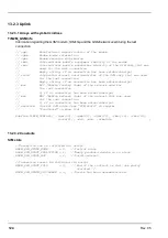
Page 277: ... Hauptstrasse 7 3244 Ruprechtshofen Austria Europe Tel 43 0 2756 7718023 support microtronics com www microtronics com Microtronics Engineering GmbH Headquarters Hauptstrasse 7 3244 Ruprechtshofen Austria Europe Tel 43 0 2756 77180 Fax 43 0 2756 7718033 office microtronics com www microtronics com Rev 05 277 ...

Page 278: ...01 2011 for myDatanet TÜV SÜD ATEX Directive 2014 34 EU Microtronics Engineering GmbH All rights reserved Photos Microtronics 300574 Rev 05 Microtronics Engineering GmbH www microtronics com Hauptstrasse 7 3244 Ruprechtshofen Austria 43 2756 77180 office microtronics com ...

Reviews: