background image


Operating Instructions Thread tapping units/ Accessoriesr 01/09, Software 4.9 

©  

01.1994-2016 microtap GmbH 

59 

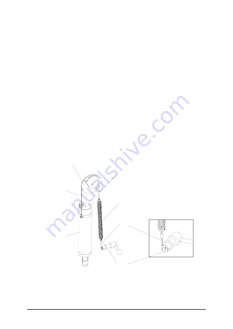
•  Cable 2 (retaining spring (C) -> eccentric pulley (B) 
-  Engage the looped end of the cable (2) with the retaining spring (2) 

Insert  the cable (2) end with the nipple and fix it in the excentre pulley (B) 

 
•  Cable 1 ( adjusting lever (D) -> retaining spring (C)  
-  Insert  the cable (1) end with the nipple into the radial hole of the adjusting 

lever (D). 

-  Engage the looped end of the cable (1) with the retaining spring (C) 
 
•  Cable 3 (eccentric pulley (B) and motor bracket (A) 
-  Insert  the cable (3) end with the nipple and fix it in the excentre pulley (B) 
-  insert the new cable (3) end with the nipple into the hole located at the larger 

diameter of the eccentric pulley (B) and secure it in place by tightening the 
grub screw. 

-   Insert  the cable end with the nipple and fix it in the eccentric pulley. 
 

6.  Remove the supporting wooden block and test the floating action of the work 

head. 

7.  Close machine (see chapter “closing machine”) 

3

B

2

1

D

A

C


Summary of Contents for Jobtap

Page 1: ...Operating Instructions Thread tapping units Accessoriesr 01 09 Software 4 9 01 1994 2016 microtap GmbH Operation Instructions microtap II megatap II jobtap ...

Page 2: ...either the entire operating instructions nor any parts thereof may be communicated directly or indirectly to third parties nor may they be copied or used other than for the purpose for which they are supplied General information list of contents 1 SAFETY INSTRUCTIONS Technical data 2 Description Assembly 3 Commissioning Operation machine 4 Maintenance 5 Trouble shooting 6 Spare parts 7 Integration...

Page 3: ...microtap II 15 2 1 3 Dimensions base plate 16 2 2 Short description of the machine 17 2 2 1 The automatic thread tapping machine has the following distinguishing features 18 2 2 2 Rear side of machine head megatap II microtap II 19 2 3 Thread tapping terms 20 2 4 Static fracture torque of taps 23 3 ASSEMBLY COMMISSIONING AND RELOCATION 24 3 1 Off loading and unboxing 24 3 2 Commissioning 25 3 2 1 ...

Page 4: ... 39 4 4 Setting changing the parameter 40 4 4 1 Operating menu 40 4 4 2 Parameter Menu 40 4 5 Manual operation 48 4 6 Thread tapping with option ZAP via remote control 49 4 7 Thread tapping with ZAP option via RS232 50 5 MAINTENANCE 51 5 1 Periodic routine maintenance 51 5 1 1 Replacing the dust filter only megatap II jobtap labtap 51 6 TROUBLE SHOOTING 52 6 1 General information 52 6 2 Fault repo...

Page 5: ...p II 66 8 3 Depth stop 69 8 3 1 Setting of the depth stop 70 8 3 2 Working in ZAP mode with depth stop 70 8 4 DSK double spindle head 71 8 4 1 Installing double spindle head onto the machine 71 8 4 2 Adjusting the hole centres 71 8 4 3 Installing of collet and tool 72 8 4 4 Maintenance 72 8 5 LSM Air seal for exit of motor spindle 73 8 5 1 Mounting of air seal 73 8 6 Air Blast unit 75 9 PRODUCT OV...

Page 6: ...d health related EC regulations This declaration is void if alterations are performed on the machine without prior agreement with microtap GmbH machine term Tapping machine machine type microtap II megatap II labtap jobtap machine serial No xxxxxx x Applied EC standards EC machine regulation 2006 42 EG 89 392 EWG EC low voltage regulation 2006 95 EG 73 23 EWG EC regulation electromagnetic compatib...

Page 7: ...chen will be liable as manufacturer to grant a 12 month warranty according to the product liability law dated 01 01 89 and in the range of our own delivery conditions provided that the copy of this warranty certificate will be returned to us immediately after taking the a m machine into operation By sending this certificate with your signature back to us you acknowledge the receipt of a m machine ...

Page 8: ...responsibility The machine must be assembled operated maintained and repaired only by authorised and trained personnel allocated to the task The safety equipment attached to the machine must not be modified or disabled Retrofits or modifications of the machine may be carried out only following prior agreement with and in accordance with instructions issued by microtap GmbH The user shall bear full...

Page 9: ...sregarded can result in machine errors CAUTION This symbol identifies operating instructions which must be followed exactly to avoid damage to the machine its control system or peripheral system components WARNING This symbol identifies operating instructions which must be followed exactly to avoid risks of injury to personnel it includes the definition of CAUTION Failure to observe such instructi...

Page 10: ...tions in Germany VBG must be observed and complied with Risk of electric shock through contact with conducting components through assembly of the machine EN 60204 VDE 0113 through contact with conducting components following inexpert maintenance VBG 4 Risk of thermal shock by touching the tap immediately after the tapping process Risk from materials of components or work materials through contact ...

Page 11: ...ny changes of or with the machine which may have an impact on its safety The management of the user company is under the obligation to operate the machine only if it is technically sound faults which may impair safety of operation must be rectified immediately The management of the user company must ensure a proper work place environment through appropriate work regulations and inspections The man...

Page 12: ...y barrier cream before starting work If your skin comes into contact with lubricants safety materials or cleaning fluids immediately wash the affected part with soap and water or apply a greasy skin cream Provision must be made to avoid lubricants and safety materials from getting into the waste water drains Safety instructions Every container of lubricant or ancillary material for instance cleani...

Page 13: ...ry compressed air ZAP mode min 2 bar 58 psi max 8 bar 116 psi Dry compressed air drop spray mode min 4 bar 58 psi max 8 bar 116 psi Torque rates Version microtap II G2 2 to 65 Ncm Version microtap II G5 jobtap labtap 5 to 220 Ncm Version megatap II G8 jobtap labtap 50 to 700 Ncm Version megatap II G14 jobtap 120 to 1 680 Ncm Version megatap II G16 jobtap 150 to 2 100 Ncm Cutting speeds Version mic...

Page 14: ...8 jobtap labtap 27 0 Machine head megatap II G14 G16 jobtap 28 6 Tool attachment system Machine type Spindle Tool holder microtap II G2 B6 Collet change system SZS0 microtap II G5 jobtap labtap B10 Quick tool change system SWS0 megatap II G8 jobtap labtap B12 Quick tool change system SWS1 megatap II G14 jobtap B12 Quick tool change system SWS2 megatap II G16 jobtap B12 Quick tool change system SWS...

Page 15: ...tandard thread M 3 5 M 14 9SMn28 DIN 13 sheet 34 M 3 5 M 18 AlCuMgPb megatap II G16 jobtap M 4 M 14 X5CrNi189 Metric ISO standard thread M 4 M 16 9SMn28 DIN 13 sheet 34 M 4 M 20 AlCuMgPb Peripheral operating conditions Room temperature for the machine 0 to 60 C 32 to 140 F Isolation IP 44 Continuous noise emittance 70 dB A measured with continuous ZAP operation Reference meter Onsoku Sand Meter SM...

Page 16: ...Operating Instructions Thread tapping units Accessoriesr 01 09 Software 4 9 01 1994 2016 microtap GmbH 14 2 1 1 Dimensions megatap II Fig 2 1 Dimensions megatap II jobtap labtap unit mm ...

Page 17: ...Operating Instructions Thread tapping units Accessoriesr 01 09 Software 4 9 01 1994 2016 microtap GmbH 15 2 1 2 Dimensions microtap II Fig 2 2 Dimensions microtap II jobtap G5 labtap G5 unit mm ...

Page 18: ... tapping units Accessoriesr 01 09 Software 4 9 01 1994 2016 microtap GmbH 16 2 1 3 Dimensions base plate Fig 2 3 Dimensions Standard base plate for all thread tapping machines Threaded connection G PG6 for reassembly of lubricants ...

Page 19: ...tap II G5 jobtap G5 1 Base plate 7 Setting lever for retracting force on drive spindle counter balance 2 Height adjustment column 8 Drive spindle 3 Thread tapping unit 9 Quick change collet holder 4 Crank for height adjustment 10 control panel and display screen 5 Clamp handle for height adjustment 11 EMERCENCY STOP switch megatap II main switch 6 Operating lever with start button 12 Motor ON OFF ...

Page 20: ... megatap II G14 G16 jobtap G14 G16 includes a gearbox between the drive motor and the work spindle Continuous monitoring of torque of drive motor The torque is limited to the value preset by the operator and is continuously indicated on the operator display The torque is monitored to prevent fracture of the tool to provide for instance a measure of tool quality and tool life or indication whether ...

Page 21: ...ess sensor ZAP PIN1 red 2 Receptacle I O user interface SPS I O 10 Setting lever for retracting force counter balance 3 Receptacle V24 RS 232D serial interface 11 Receptacle Operating lever 4 Receptacle lubrication unit MMS 12 Receptacle Foot switch ZAP 5 Receptacle Main connection 230VAC 50Hz 13 Key switch option 6 Fuse megatapII 16A T microtapII 3 15A TT 14 cable relief 7 MMS connection 15 Air i...

Page 22: ...f the thread 7 Cutr Cut relief The thread tapping process is influenced by several interacting parameters the part being tapped and the material it is made of the kind and type of tool used the spindle speed the thread depth the drill diameter of hole whether or not chips are removed the lubricant The findings revealed the following facts it is not possible to compile a general applicable table of...

Page 23: ...atically resume tapping in an attempt to complete the thread to the desired depth If three attempts fail the tool reverses completely out of the workpiece and a related error message appears on the machine display min Mz torque applied to the workpiece The min Mz value should be set to about 35 of the max Mz values in Ncm normally required to tap the thread Whenever the actual operating torque fai...

Page 24: ...feature helps you to establish the best spindle speed for any given job by carrying out tests at different spindle speeds The same test method applies for finding the best lubricant and tool type 6 DEPTH depth of thread This value determines the depth of the thread tapped in the workpiece 7 CUTR cut relief This menu prompt determines how often the spindle should reverse in the course of tapping op...

Page 25: ...1900 1100 1300 800 1100 Ncm M8 Bottom holes 3000 4200 2500 3500 2000 3000 Ncm Through holes 3000 5000 2500 4000 2000 3400 Ncm M10 Bottom holes 7400 7000 6000 Ncm Through holes 8300 7200 6400 Ncm NOTE The classification of thread tapping tools into high standard and low quality is meant for general guidance and not as technical specifications Participation for machines with gear reductions Type G14...

Page 26: ...l weight article incl packing materials Operating head microtap II megatap II G8 megatap II G14 16 585 x 355 x 360 700 x 400 x 410 700 x 400 x 410 18 1 kg 27 0 kg 28 6 kg 2 1 kg 3 2 kg 3 2 kg 21 5 kg 31 6 kg 35 1 kg 47 4 lb 69 7 lb 77 4 lb base plate 625 x 430 x 110 20 5 kg 3 0 kg 23 5 kg 51 8 lb Column 600 mm long 960 x 255 x 335 12 8 kg 2 6 kg 15 4 kg 34 0 lb Column 750 mm long 960 x 255 x 335 1...

Page 27: ... W x H 1470 x 1320 x min 1600mm 2 Further important requirements electric mains supply 230 VAc 10 50 60 Hz optional microtap II G2 G5 115VAC 10 Max allowable surface level tolerance 3 mm m vibrationless interferenceless HF emissions free from local directional heating or cooling from radiators draft air etc ambient room temperature must not exceed 30 C relative humidity must not exceed 80 a supply...

Page 28: ...ad on the height adjustment bracket using 4 screws and washers M6 Tighten the hexagon socket screws with a torque of 10 5 Nm 5 Connect the start button cable in the operating lever into the appropriate receptacle only megatap II 6 Connect the mains power cable with the appropriate receptacle CAUTION The wall outlet must be protected with a 16A automatic circuit breaker 7 Turn the key switch into t...

Page 29: ...hen be lifted with appropriate resources and be moved to the new operating area WARNING The weight of the machine depends on the type and the column between 60 and 80 kg 7 If applicable plug in the foot switch plug in the remote control cable and the PC cable 8 Plug in the mains cable CAUTION The supply socket must incorporate a 16 A automatic circuit breaker 9 Turn the key switch to the desired p...

Page 30: ...s female Figure please see chapter technical data description PIN Connection 2 open collector 3 24 V max 0 2 A Any 24 VDC solenoid valve of appropriate capacity can be connected between pins 2 and 3 for instance for an external lubricating system or control for compressed air etc 3 4 2 Serial interface RS 232 SUB D 9 pin female Figure please see chapter technical data description 9600 baud 8Bit no...

Page 31: ...he operating area of the machine when it is under remote control by erecting a fence photo electric gate or other means of barrier PIN Connection 1 Relay 1 contact A contact closed machine ready 9 External input 1 2 Relay 2 contact A contact closed quality OK 10 External input 2 3 Relay 3 contact A contact open 11 External input 3 4 Relay 4 contact A contact open 12 External input 4 5 Common refer...

Page 32: ...units Accessoriesr 01 09 Software 4 9 01 1994 2016 microtap GmbH 30 3 4 4 I O wiring diagramm internal wiring of the machine Information about the internal wiring of the I O interface microtap II G5 valid for software version 4 9 and higher ...

Page 33: ...pping units Accessoriesr 01 09 Software 4 9 01 1994 2016 microtap GmbH 31 Information about the internal wiring of the I O and ZAP interface microtapII G5 valid only for software up to version 4 0 megatapII ZAP Interface I O interface ...

Page 34: ...r ZAP megatapII External wiring of the ZAP interface microtap II G5 valid only for software up to version 4 0 megatap II Attention for microtapII G5 Connector for valve 3 is located at the I O interface for software up to version 4 0 see sample 1B 3 4 5 2 Sample 1B magnetic valve V3 to connector I O microtapII External wiring of the I O interface microtapII G5 valid for software version 4 9 and hi...

Page 35: ...tware Option Input 1 4 active high The inputs 1 4 are wired against PIN 6 GND Ext Start 1 2 active low The inputs Start 1 2 are wired against PIN 7 24V In ZAP Mode Start Fz Start Auto Sz autostart Fz Sz the pneumatic valve for the pneumatic Z Axis spindle feed is actual when the closer Start 2 is activated 3 4 5 5 Sample 3A Exit relay contact K1S ready by internal 24V power source 3 4 5 6 Sample 3...

Page 36: ...ol selected parameter value The end of each parameter datum is coded by the characters CR carriage return No parity sum created EXAMPLE T 105 CR depth 10 5 mm The set of parameters includes the following parameters Parameter Code Range of values Depth T 0 800 0 0 80 0 mm Spindle speed N 300 3000 300 3000 min 1 Fracture torque B 30 7000 30 7000 Ncm chip clearance E 0 5 0 5 chip clearances Lubricant...

Page 37: ... machine responds then with the same code and its current value EXAMPLE Q 2 CR The following values are monitored exactly Value Code Value range Mz cut compl cut process forerun c values cut Ncm Mz compl cut process forerun and reversal C values cut Ncm Type of machine W 0 1 2 0 G8 1 G14 2 G16 2 G5 Mz max max torque during cut M 30 7000 30 7000 Ncm Mz max max torque during reverse Y 30 7000 30 700...

Page 38: ...In special applications further information can be retreived Quality status Additional requests Code used 1 tapping depth reached t 5 no of reversing attempts r 6 Sz s 3 5 5 Remote control mode The thread tapping machine can be remote controlled For this mode the option ZAP has to be installed see chapter integrating options Also the operation via the machine control panel is then disabled Remote ...

Page 39: ...ollowing operations because when the machine is in automatic mode the spindle can start automatically 2 Change the taps as follows Push the sleeve B of the quick changer collet a upwards and remove the quick change insert c and the existing tap e Change tool e in the quick change insert c Insert the new tap e with the quick change insert c so that the bar d on its shank engages with the groove in ...

Page 40: ...he EMERGENCY STOP button pull it outwards 2 Turn on the main switch at the rear side microtap II on front side megatap II of the machine 3 Upon start the machine performs a self test routine 1 2 3 4 5 6 DISPLAY Button Function 1 3 Selector key 4 Menu choice 5 indicator active rotary knob 6 rotary knob digital potentiometer 7 BACK to working menu from every menu Please note that only lightning butt...

Page 41: ...e selector switch under the word NEW if you would like to create a new program 6 Press the selector switch under the word LAST if you would like to work with the last parameter setting 7 Version megatap II Set the drive selector switch to 1 8 The machine is now ready for operation in the standard settings 4 3 System Setup 1 Turn on the main switch of the operating head and at the same time press a...

Page 42: ...n Now all selector keys are lightning It is possible to cut a thread with these settings If you would like to form a thread or cut a left thread you have to do like the following NOTE The machine will only operate in the operating menu 4 4 2 Parameter Menu Press soft key 4 menu choice Dial with the rotary knob 6 the desired function the arrow shows the selected menu To select the menu press the se...

Page 43: ...message Depth not reached appears on the display THREAD FORMING The spindle forms the tap to the depth which is set before If Mz max 10 is reached the spindle reverses and the error message Depth not reached appears on the display The reduce of 10 of the Mz prevents the tool clamp at reversal Display in working menu FORMING THREAD INSERT Mz Spindle turns in the thread insert till Mz max is reached...

Page 44: ...ssing selector key 3 4 4 2 3 Start Setup The Start Setup depends on the options of the maschine Without ZAP with ZAP START MANUAL START AUTO Sz START MANUAL START AUTO Sz START Fz Sz Start Manual without ZAP Spindle starts with start button Display in the working menu Start MAN Start manuallly The reference point will be set to zero by the start button in the operating lever Start Auto Sz Spindle ...

Page 45: ...ata memory when the machine is switched on next time If it is not possible to cut the pressure cylinder switches off after max 3 seconds The motor drives back The error message QUALITY CONTROL NO LEAD ANGLE appears Start Fz with Option ZAP In manual operation the function is the same like in Start Manual START after Fz force is reached Fz 010 Display in working menu START Fz Operate selector key 1...

Page 46: ...ches off and the spindle reverses The spindle goes back The error message QUALITY CONTROL NO LEAD ANGLE appears 4 4 2 4 LUBRI CYCLE ESCAPE MODE TIMES SME DROP 1 1 ESCAPE MODE TIME TIMES SPRAY 010 1 1 Choose the lubricant unit with selector key 1 In case of a SPE set the duration of the lubricant impulse with selector key 2 and rotary knob 6 Define frequency of the lubricant cycle every thread or e...

Page 47: ...ctor key 3 and set the number of threads part with rotary knob 6 To clear push selector key 2 00000 P COUNTER 00000 G DEPTH 1 min M 4 5 0 10 mm 1000R 0150Ncm Working menu with active counter See at the left side of the display the number of finished parts Right side number of finished threads each part In the case of scrap it is possible to reset the thread counter not the part counter with escape...

Page 48: ...file can be stored if all 10 digits have been edited with selector key 1 all selector keys are shining Store Press selector key 2 the storage will be confirmed with a short OK on the display Recall Push selector key 3 If a valid data file has been selected a short OK appears in the display If the data file is empty NO DATA will be displayed NOTE The spindle distance travel Sz will not be stored 4 ...

Page 49: ...y 3 print actual store AUTOMATION for customer specific functions p e automatic vice Switch program on or off with selector key 1 The program is preset with the following function If the spindle is not in the start position the exit V3 is active see chapter I O I O wiring diagram STARTSIGNAL Switch program on or off with selector key 1 This parameter is needed for the use with WinPCA Version from ...

Page 50: ...NG The selected limiting torque must always be less than the fracture torque of the tool If you fail to observe this rule the tool may break when reaching the bottom of a ground hole Small broken off particles of the tapping tool can turn into dangerous bullets 6 Wear eye protection 7 With the operating lever lower the tool until it touches the pilot hole 8 Apply necessary cutting start force to t...

Page 51: ... or start manually with push button Press foot switch until the spindle reaches the material The spindle starts to work if the preset Fz force is reached the feeding speed can be set with an adjusting srew on the valve 5 Insert desired tool 6 If needed set retracting force with lever of the spring balance system 7 Mount workpiece NOTE Leave a distance of at least 5 mm between workpiece and tool 8 ...

Page 52: ...5 mm distance between tap and workpiece 7 Key in the desired process parameters in the operating menu thread depth spindle speed limiting torque max Mz WARNING The selected limiting torque must always be less than the fracture torque of the tool If you fail to observe this rule the tool my break when reaching the bottom of the ground hole Small particles can turn into dangerous bullets 8 Wear eye ...

Page 53: ...ely essential that SAFETY REGULATIONS are observed and obeyed Location period Task Remarks half if yearly needed Dust filter X X replace only megatap II jobtap labtap WARNING DO NOT USE COMPRESSED AIR or other media likely to attack the machine paint coating 5 1 1 Replacing the dust filter only megatap II jobtap labtap 1 Finish current task and switch off the machine 2 Remove the dust filter from ...

Page 54: ... service department will gladly assist you To help us assist please report machine type serial number and software version when contacting us microtap GmbH Customer Service Rotwandweg 4 82024 Taufkirchen Germany Customer Service Phone 49 89 612 8051 Fax 49 89 612 7488 Email info microtap de Return repair delivery to microtap GmbH If you need to return the machine to microtap GmbH for repair please...

Page 55: ...ault report form Machine type Machine No Name and address of sender Person to contact phone Fax email Contents of return shipment Work head Mains cable tick as appropriate send only if it doesn t work Column 600 mm 750 mm 1000 mm Foot switch Lubricant system Which fault occurs Please give full detaill When where at what interval ambient temperature is the machine remotely operated etc ...

Page 56: ... to 0 Set drive selector switch to 1 see also chapter Changing tap USER ABORTED DEPTH 1 min M 4 5 0 10mm 1000R 0150NCM Meaning Remedy User aborted thread tapping Restart thread tapping after solving the problem COUNTER ACHIEVED XXXX THREADS DEPTH 1 MIN M 4 5 0 10mm 1000R 0150NCM Meaning Remedy Preset production quantity is reached Press illuminated associated push button xxx Number of reversals DE...

Page 57: ...ck thread if it is o k QUALITY CONTROL NO LEAD ANGLE Meaning Remedy Tap failed to start cutting Check if workpiece is present Check if hole is present Check if hole is oversized Check if tool is present Check if Sz and Sz are correctly preset Auto start only QUALITY CONTROL ERROR SZ 0000 Meaning Remedy Tap failed to start cutting Check if Sz and Sz are correctly preset check if Sz is out of the pr...

Page 58: ...ain or hardware error 2 Machine needs to be repaired by the service of microtap GmbH HARDWARETEST FAILED ERROR 003 Meaning Remedy Error Electronic defective Machine needs to be repaired by the service of microtap GmbH HARDWARETEST FAILED ERROR 004 Meaning Remedy Error Electronic defective Machine needs to be repaired by the service of microtap GmbH WARNING If the error message ERROR appears the el...

Page 59: ...1 5 Remove the retaining screws of the spindle cover at the bottom of the work head and withdraw the cover downwards CAUTION Support the cover with one hand while removing the last retaining screw Have a look to the cables to make sure they are not broken CAUTION Support the front panel while unplugging cable connections The panel may be subject to static discharge Do not touch the components moun...

Page 60: ...nd must be serviced by microtap For continued protection against fire hazard replace only with the same type and rating of fuse 6 5 2 Changing the suspension wires The floating suspension comprises a tension spring C three wire cables 1 3 an eccentric cam B and an adjusting lever D If any one of the cables breaks the drive unit A can no longer float and will drop In that event replace all three wi...

Page 61: ...ole of the adjusting lever D Engage the looped end of the cable 1 with the retaining spring C Cable 3 eccentric pulley B and motor bracket A Insert the cable 3 end with the nipple and fix it in the excentre pulley B insert the new cable 3 end with the nipple into the hole located at the larger diameter of the eccentric pulley B and secure it in place by tightening the grub screw Insert the cable e...

Page 62: ...s list are those components which in light of current experience may be required mechanical and electronical spare parts parts and components required for routine maintenance All other parts are installed exclusively by microtap GmbH 7 2 Ordering spare parts The following information is required to order spare parts machine type part number description required quantity ...

Page 63: ...lter Vlies blue white 2 LTZ106 suspension wire system mic II G5 2 LTZ102 suspension wire system meg II G8 G14 G16 3 JOX077 Tension spring mic II G5 3 JOX076 Tension spring meg II G8 G14 G16 4 DOX005 Start button mic II meg II 4 DOX006 Silicon cover for Start button 5 DOX111 Fuse 3 15A TT mic II 230VAC 5 DOX113 Fuse 16A T meg II 230VAC 5 DOX114 Fuse 6 3A T mic II 115VAC ...

Page 64: ...nd fill it with required lubricant Open the quantity regulator of the micro pump C approx 2 turns more lubrificant turn right Start spray pulses by manual operation srew driver using the valve rear side of MMS just until lubricant comes out Reduce quantity regulation C in accordance with required quantity Adjust nozzle A so that the lubricant cone impacts to a sheet of paper or a cloth Adjust quan...

Page 65: ...ay regulator B and the time parameter menu lubricant pulse does not influence the lubricant quantity An impulse generator is available as an accessorry Manufacturer hint Always lubricate generously so that deep threads are fully lubricated and so that there is enough lubricant for the reverse stroke Lubrication improves the quality of the thread and extends the service life of the tap ...

Page 66: ...e operating the machine Chips and dirt during blow out can injure the eyes e The blow out puls starts when the spindle reaches the upper endposition and when the machine is switched on f The time duration of the air pules can be set by the potentiometer E at the connnector D with a slot screwdriver g The quantity of the air can be changed by the flow control G h Install the O ring 48mm x 4mm that ...

Page 67: ...t MMS 3 Select in settings Lubr Cycle MODE SME DROP Times 4 The break time of the lubricant cycle can be set by the setting screw H at the pulse K by a slot screwdriver The times of the lubricant cycle can be set by each process 5 The lubrication takes place only during process not in reversal Manufacturer hint The pulse control is needed to produce depht threads and reaches good results if in the...

Page 68: ...eft and right are defined from the rear side of the machine b e c a 1 Switch off the machine 2 Disengage the main connector a 3 Remove the cover plate b from the back of the machine 4 Remove the air filter housing c 5 Install the cutting start force sensor A Insert the plug A16 so that the lead is at the right side Secure the cutting start force sensor A with two hexagon socket screws A19 M4 x 40 ...

Page 69: ...he ZAP control cable L to the I O Port d of the machine 8 Fix the ZAP control cable L with the cable clamp K 9 Reinstall the air filter housing c ATTENTION The filter pad must be inserted 10 Insert the cable W1 of the foot switch W to the sleeve f 11 Connect the pipe V to the screw E and to a service unit with kondensed water regulate pressure min 2 bar max 8 bar 12 Engage the main connector a and...

Page 70: ... F G H C R Q P O N M K J I U A T S A1 A2 A3 A5 A6 A8 A10 A11 A13 A12 A9 A7 A14 A15 A17 A18 A19 A12 A16 A4 L2 L L1 W1 W W2 V V1 V2 Pos Artikel Nr Pos Artikel Nr A FRX001 L1 GOX060 A2 JOX051 M GOX177 A11 BOX001 N GOX013 A16 DMX002 O GOX315 C GOX306 Q GOX053 D GOX165 R GOX176 E GOX175 V GOX312 G GOX106 W LTZ104 H GOX315 W1 DMX001 L LTZ105 W2 DOX013 ...

Page 71: ...ith machine type jobtap Application areas restricted drill applications drilling counter sinking rearning A B C D E A C D B E active Not active C B D E WARNING Risk of injury Use the flap B only with the program continous run Use the depth stop only with the program continous run Incorrect use could cause injury damage to the tool workpiece and machine ...

Page 72: ...e a gauge block between spindle C and stop post E with the desired working depth Rotate spindle C just to the gauge block and secure the spindle C with nut D 5 Set desired depth torque and speed in the working menu NOTE When the working spindle reaches the preset torque it stops If the spindle does not move for 5 10 seconds the working process stops 8 3 2 Working in ZAP mode with depth stop 1 In Z...

Page 73: ...Locate double spindle head A with flange D up to the motor G until the driver insert C locks in the driver slot of the double spindle head A rotate if necessary 3 Clamp flange with fixing srew F 4 Adjust counter balance system using lever 8 4 2 Adjusting the hole centres 1 Loosen the central nut of the spindle housing 1 with hexagonal key 3 2 Turn the spindle housing with spanner 2 until the desir...

Page 74: ...ool and clamp it with key 9 secure spindle with key 2 Do not over tighten 4 To stop the tap slipping it should be fixed in the spindle 6 tighten grub screw 10 with socket key 11 ATTENTION Never fit the collet nut 8 to spindle when the collet 4 is not positioned correctly in the collet nut 8 4 4 Maintenance The gear has an oil lubrication Before installation check oil level Hold the double spindle ...

Page 75: ...ior of the machine and will be used at the following working conditions Use of compressed air under the spindle Short chip materials dirty contarminated air ie welds Atomised lubricants 8 5 1 Mounting of air seal a a b 2 Switch off the machine 3 Disengage the main connector 4 Unscrew the coverplate of the spindle b at the underside of the machine head 4 screws a M3 x 10 with hexagon socket Luft Ai...

Page 76: ...t screws E M3 x 12 6 Adjust air seal so that there is a evenly air gap between spindle c and air seal A or B To control the air gap move the hand lever d up and down 7 Fix the screws E Attention Not too tight aluminium cover 8 Install air hose D to throttle C and to a maintenance unit with condensed water separator max 8 bar 9 Adjust outcoming air with throttle C so that there is an easy airflow 1...

Page 77: ... eyes during blowing out e The air blast impulse starts when the working spindle reaches the upper back position and also when the machine is first switched on f The time duration of the air impulse can be set with the potentiometer at the 15 pol SUB D connector using a screw driver g Air quantity can be changed using the throttle right beside the quantity regulation of the micropump from the MMS ...

Page 78: ...nd slow reverse speeds Automatic start with position depth control with ZAP Cutting force FZ start sensor only with optional ZAP User data storage for 40 different parameters Lubricant control with pulse and with timed flow Variable chip clearance function Titanium chip function Single and total thread part counter SW Program for thread cutting and forming SW Program for thread inserts Ensat Helic...

Page 79: ...SM air seal MLM machine light SHV column specials HVS horizontal reach adjustment only microtap II only microtap II only microtap II SSB security key only megatap II only megatap II only megatap II SWS quick change tool holder systems ASL audible signal light Inserts inserts and screw holder systems MPT manual positioning table not controlled WinPCA Data Acquisition Software for PC QND ONLINE seri...

Page 80: ...1 1 8 M 3 5 00 01 01 2 8 2 1 M 2 2 6 M 4 00 01 01 3 5 2 7 M 3 M 4 5 5 00 01 01 4 0 3 0 M 3 5 00 01 01 4 5 3 4 M 4 M 6 00 01 01 03 5 5 4 3 M 7 00 01 01 6 0 4 9 M 4 5 6 M 8 00 01 01 03 7 0 5 5 M 7 M 9 10 00 01 01 03 8 0 6 2 M 8 M 11 00 01 01 03 9 0 7 0 M 9 M 12 01 01 03 10 0 8 0 M 10 00 01 01 03 11 0 9 0 M 14 01 01 03 12 0 9 0 M 16 01 01 03 14 0 11 0 M 18 03 16 0 12 0 M 20 03 18 0 14 5 M 22 26 03 SW...

Page 81: ...microtap II G2 Collet chuck system Size ER8 holder with 4 collets M0 3 M3 Standard SZS0 Collet Type L D Size D2 Range ER 8 13 5 8 5 1 0 5 0 0 5 ER 11 18 11 5 1 0 7 0 0 5 ER 16 28 17 1 0 3 0 4 0 10 0 0 5 1 0 ER 20 32 21 1 0 3 0 4 0 13 0 0 5 1 0 Collet holder type Chuck range D2 D D1 L2 00 ER 11 0 5 7 0 19 13 23 01 ER 20 0 5 13 34 19 38 ...

Reviews: