Board Components and Settings
1 0
R e v i s i o n 3
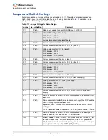
Jumper and Switch Settings
Recommended default jumper settings are defined in
. The voltage selection jumpers are
highlighted in grey. Connect jumpers in the default settings described in
to enable the pre-
programmed demo design to function correctly.
Table 1-1 • Jumper Settings for Demo Design
Jumper
Default Setting
Comment
JP1
Pin 2-3
Main power supply. Connect Wall/USB input to VCC_IN.
JP2
Pin 2-3
VCC CORE voltage (1.2 / 1.5 V)
Pin 2-3 selects 1.2 V.
Pin 1-2 selects 1.5 V.
Jumper is on upper right area of board.
JP3
Pin 2-3
Current measurement header for Bank 0
JP4
Pin 2-3
Current measurement header for VCC_B2 (Bank 2)
JP5
Pin 1-2
Voltage selection for VCC B0 (Bank 0)
Pin 1-2 selects 3.3 V.
Pin 3-4 selects 2.5 V.
Pin 5-6 selects VCC_CORE.
JP6
Pin 2-3
Current measurement header for Bank 1
JP7
Pin 2-3
Current measurement header for VCC_B3 (Bank 3)
JP8
Pin 1-2
Voltage selection for VCC B1 (Bank 1)
Pin 1-2 selects 3.3 V.
Pin 3-4 selects 2.5 V.
Pin 5-6 selects VCC_CORE.
JP9
Pin 2-3
Current measurement header for JTAG supply.
JP10
Pin 2-3
Current measurement header for VCC (FPGA core supply).
JP11
Pin 1-2
Voltage selection for VCC JTAG (JTAG supply.
Pin 1-2 selects 3.3 V.
Pin 3-4 selects 2.5V.
Pin 5-6 selects VCC_CORE.
JP12
Pin 2-3
Current measurement header for VCC_PUMP (FPGA charge pump
supply)
JP13
Pin 1-2
Remove each short default jumper to disconnect any of the 8 LEDs from
the FPGA.
JP14
Pin 1-2
Remove each short default jumper to disconnect any of the 8 DIP switches
SW3.1 through SW3.8 from the FPGA.
By default, SW3.1 through SW3.8 should all be closed (set to the ON
settings).
The 8 DIP switches are connected to the 8 LEDs (LED1, LED2, … LED8).
JP15
Pin 1-2
Remove each short default jumper to disconnect any of the four push-
button switches, SW4 through SW7, from the FPGA.
SW1
OFF
Flash*Freeze
: To enable Flash*Freeze mode, slide SW1 toward FF_ON.
In Flash*Freeze mode, current consumption of the FPGA goes below
50 µA. Current can be measured by placing a current meter between [pin1
or pin 2] and [pin 3 or pin 4] of JP10 (VCC_CORE).
Summary of Contents for IGLOO nano Starter Kit
Page 1: ...IGLOO nano Starter Kit User s Guide ...
Page 6: ......
Page 9: ...IGLOO nano Starter Kit Revision 3 9 Figure 1 3 Bottom Silkscreen ...
Page 14: ......
Page 28: ......
Page 30: ......
Page 32: ......
Page 34: ......
Page 36: ......
Page 41: ......

