


Chapter
2
System Components
2-20
Vision HAWK Smart Camera Guide
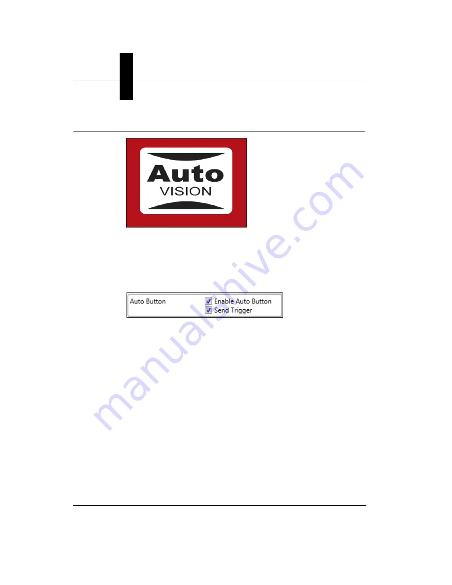
AutoVISION Button
The AutoVISION Button has two positions, selectable by the length of
time the button is held down, and indicated by one or two beeps in
succession. It can also be used to send a trigger signal when
Send
Trigger
is checked in AutoVISION software’s
Connect
view. When the
trigger functionality is enabled, pushing the AutoVISION Button triggers
the camera to capture an image.
1st Position: Red Targeting Pattern
The first AutoVISION Button position turns the targeting system on.
This overrides any other targeting modes that have been configured.
2nd Position: Auto Calibration
The second AutoVISION Button position starts the Auto Calibration
process, which selects the appropriate photometry and focus settings
for the camera. The selected values are then saved for power-on.
Summary of Contents for Vision HAWK
Page 1: ...Vision HAWK Smart Camera Guide 83 016800 02 Rev C ...
Page 6: ...Preface vi Vision HAWK Smart Camera Guide ...
Page 22: ...Chapter 2 System Components 2 12 Vision HAWK Smart Camera Guide NPN Output for External Load ...
Page 24: ...Chapter 2 System Components 2 14 Vision HAWK Smart Camera Guide PNP Output for External Load ...
Page 26: ...Chapter 2 System Components 2 16 Vision HAWK Smart Camera Guide PNP ...
Page 36: ...Chapter 2 System Components 2 26 Vision HAWK Smart Camera Guide ...
Page 42: ...Chapter 3 Optics and Lighting 3 6 Vision HAWK Smart Camera Guide ...
Page 46: ...Appendix A Connector Pinouts A 4 Vision HAWK Smart Camera Guide ...
Page 52: ...Appendix B Cable Specifications B 6 Vision HAWK Smart Camera Guide ...
Page 60: ...Appendix C General Specifications C 8 Vision HAWK Smart Camera Guide ...